Choosing the right wire mesh cable tray in China takes more than comparing prices. The tray must suit the cable load, installation environment, and route layout. A crowded factory ceiling, for example, may need a different width and support spacing than a clean office corridor. Small details matter.
A practical rule for buyers is: “Choose the tray for the route, the load, and the environment—not price alone.” I cannot responsibly attribute this original wording to a named industry expert without a verifiable source. That limitation matters. A quotation can sound authoritative while offering no evidence.
This guide explains how to assess wire diameter, mesh dimensions, finish, load capacity, and connection hardware. It also considers supplier documentation, sample inspection, and production consistency. Ask for technical data that matches the intended installation, then compare it with the actual site conditions. Check cut edges and welds on a sample. Look for a finish suited to the expected moisture and exposure. Confirm that accessories fit the tray system. A neat catalogue image is not enough.
Some choices remain uncertain until the route is surveyed. Measurements can be incomplete. That happens. Treat assumptions as questions to verify, not facts to repeat. A careful selection process helps buyers balance durability, installation effort, and total project cost when sourcing a wire mesh cable tray in China.
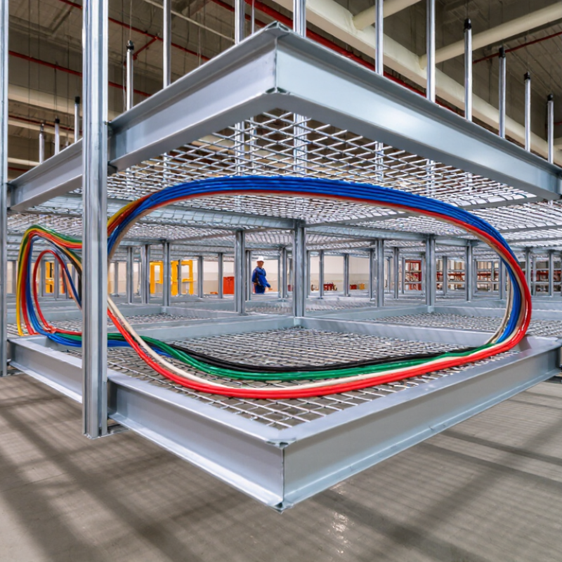
How to Choose the Best Wire Mesh Cable Tray in China?
What Is a Wire Mesh Cable Tray and Where Is It Used?
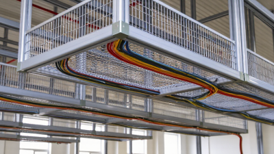
A wire mesh cable tray is an open support system made from welded steel wires. Its grid-like sides and base hold cables while allowing air to circulate around them. Compared with a solid-bottom tray, the mesh design makes it easier to see cables and spot dust or damage.
Installers often cut sections on site to fit around columns, equipment, and changing routes. The cut edges need suitable finishing to reduce sharp points and protect the metal surface. Small details matter. In practice, a tray that looks sturdy in a sample may feel less rigid across a long, unsupported span. Support spacing and cable load should be checked against project requirements, not guessed.
These trays are used in factories, commercial buildings, data rooms, and utility areas where cable routes may change. In Chinese projects, they can be found in production workshops and building services corridors, often carrying power or communication cables. They suit routes that benefit from ventilation and visual access, but they are not ideal for every environment. Moisture, corrosive chemicals, heavy cable bundles, and fire requirements may call for another material or added protection. Conditions vary. A site survey helps determine the finish, wire size, and support arrangement needed.
What Is a Wire Mesh Cable Tray and Where Is It Used?
A wire mesh cable tray is an open, welded-wire support system for routing and supporting cables. Its open structure allows airflow and makes cable inspection and changes easier. It is commonly used in commercial buildings, data and telecom rooms, industrial facilities, and other installations where accessible cable routing is needed. Suitability ratings are qualitative comparisons, not measured market data; confirm load capacity, finish, dimensions, and local code requirements for each project.
Start with the cable list, not the tray catalogue. Record cable diameters, total weight per metre, expected additions, and minimum bend radii. A tray that fits today’s cables may become crowded after one upgrade. Leave practical space for cooling and maintenance. Check the support span and load against tested capacity data; do not estimate capacity from appearance. IEC 61537:2006+A1:2017 provides requirements and test methods for cable tray systems, including mechanical performance. Ask suppliers for load tables that match the proposed width, finish, and support spacing. Details matter.
The installation environment changes the specification. For indoor dry areas, a suitable coated steel finish may be adequate; damp, coastal, or chemical settings may call for a more corrosion-resistant material or coating. Confirm this against actual exposure, not a vague “industrial” label. For outdoor runs, consider rain, sunlight, temperature changes, and wind loads on covers.
A Grand View Research cable tray market report estimated the global market at about USD 6.12 billion in 2023, reflecting broad demand across building and infrastructure projects; it does not, however, identify the right tray for a specific site.
That decision still depends on drawings, cable schedules, support spacing, and access needs. I would recheck the schedule before ordering. Small omissions can become awkward on site.
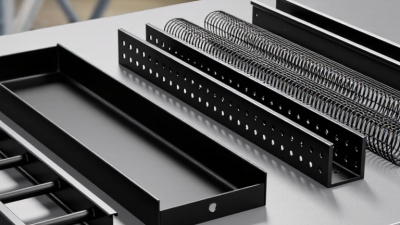
Material choice sets the tray’s strength, weight, and resistance to corrosion. Carbon steel often suits dry indoor routes and heavier cable loads. Stainless steel is useful in damp or corrosive areas, though it costs more. Aluminum is lighter and easier to handle overhead. Match the material to the actual site, not just the catalogue description. A tray near a washdown area faces different conditions from one above a clean office ceiling.
Finishes matter. Hot-dip galvanizing can protect steel in exposed settings, while electro-galvanizing is generally better suited to indoor environments. Check that cut ends and welded joints receive adequate protection; small bare spots can become the weak point. Details count. Mesh spacing affects airflow, cable support, and how easily installers can secure cables. Tighter spacing may help with smaller cables, but it can add weight and make cleaning less convenient.
Design should fit the route and load. Look at wire diameter, tray width, support span, bend radius, and accessory compatibility. For example, a loaded tray crossing a long span may need closer supports than a lightly loaded run. Ask for load data and verify it against the planned installation. Specifications do not always reflect site conditions, and that deserves a second look. A short sample section can reveal sharp edges, awkward joints, or difficult cable access before a full order is placed.
A reliable supplier should prove more than factory capacity. The ISO Survey 2022 records over one million ISO 9001 certificates in China, but certification alone cannot confirm tray quality. Ask for a current certificate, its issuing body, and the factory address it covers. Then compare the offered wire diameter, mesh spacing, weld condition, coating thickness, and load-span data with your project specification. Small details matter. A sharp weld or uneven zinc coating can complicate installation and weaken corrosion protection.
Request test reports for the exact product finish and material, not a similar sample. IEC 61537:2023 sets performance requirements and test methods for cable tray systems, including load testing. Check that reports identify the tested model, support spacing, and load, and that the test laboratory can be verified independently. Ask for batch traceability and a recent production sample; inspect cut edges, weld consistency, and dimensional tolerances. For outdoor use, discuss the exposure conditions and coating system in writing. A supplier may offer a salt-spray result, but the number of test hours is not a direct prediction of service life. I would also request one practical check: assemble a short tray section with the intended couplers and supports. It may reveal fit issues that a polished catalogue misses.
How to Choose the Best Wire Mesh Cable Tray in China?
How Should Tray Size, Accessories, and Installation Be Verified?
Verify tray size against the actual cable schedule, not a rough estimate. Record each cable’s outside diameter, quantity, weight per metre, and bend radius. Then check usable width, depth, and future capacity. IEC 61537:2006 specifies performance testing for cable tray systems, including safe working load. Compare the selected tray’s tested load rating with the cable load and support spacing. A wider tray is not automatically safer; excessive width can complicate support and cable control.
Check fittings as carefully as straight sections. Confirm that bends, tees, reducers, covers, and splice plates match the tray width and wire diameter. On site, inspect cut edges for burrs, verify joint alignment, and ensure supports sit at the spacing used for the load rating. NEMA VE 2, an installation guideline, advises following manufacturer instructions for support and connection details. Small installation differences matter.
Tips: Mock up one bend and splice before bulk installation. Pull a sample cable through it. Check clearance, sharp edges, and bonding continuity. Measurements can be imperfect; record any field changes and recheck the load calculation rather than assuming the original design still applies.
| Selection Area | What to Check | How to Verify | Practical Acceptance Guidance |
|---|---|---|---|
| Cable load | Number, outside diameter, weight, and type of cables; expected future additions; installation orientation. | Prepare a cable schedule and calculate the total cable weight per tray length. Confirm the proposed load against the supplier’s load-span data for the specified tray width, depth, material, and support spacing. | Use the manufacturer’s tested load tables for the exact configuration. Do not assume that a tray’s maximum load applies to every span or installation condition. |
| Tray width | Combined cable diameters, cable arrangement, bend requirements, and available installation space. | Compare the planned cable layout with the tray’s clear internal width. Allow room for cable separation, turning, and access where required by the project design. | Select a width that accommodates the planned installation without crowding. Confirm any fill or spacing limits with applicable electrical codes and project specifications. |
| Tray depth and mesh opening | Cable bundle depth, cable support needs, cable diameter, and the possibility of small cables slipping through the mesh. | Review the internal depth and mesh dimensions on the product drawing. Check that cable diameter and support requirements are compatible with the opening size. | Choose a depth that supports the cable bundle without obstructing covers or fittings. Use liners or another approved support solution if the cable type or project requirements call for it. |
| Material and finish | Indoor or outdoor location, moisture, chemicals, temperature, and exposure to corrosive environments. | Request material and finish specifications, such as stainless steel grade or zinc coating type and thickness. Confirm suitability against the site environment and project requirements. | Match the corrosion-protection system to the actual environment. Check compatibility of tray, fasteners, connectors, and other metal components to reduce corrosion risks. |
| Straight sections | Section length, usable length, wire diameter, edge condition, and dimensional consistency. | Compare the approved drawing and purchase specification with sample measurements. Inspect representative sections for deformation, sharp edges, and damaged coating. | Dimensions and finish should conform to the approved specification and tolerances. Handle or finish cut edges as required by the project and applicable safety rules. |
| Fittings and accessories | Bends, tees, crosses, reducers, couplers, covers, dividers, supports, and bonding components. | Check the bill of materials against the route drawings. Verify fitting dimensions, connection method, fastener compatibility, and availability of accessories for changes in direction or level. | Confirm all required fittings and supports are included before ordering. Use compatible connectors and hardware designed for the selected tray system. |
| Support spacing | Tray loading, span length, support type, ceiling or wall structure, and concentrated loads at fittings. | Review engineering calculations and the manufacturer’s load-span information. Check support locations on installation drawings, including near bends, tees, and changes in elevation. | Support spacing must follow the approved design and the applicable load data. Do not extend spans based solely on the length of the tray section. |
| Installation and routing | Route alignment, bend radius, access for cable pulling, clearance from other services, and protection from impact. | Inspect the coordinated route drawings and verify clearances at the site. Check that fittings and supports do not create sharp cable contact points or obstruct maintenance access. | Install to the approved drawings and cable manufacturer’s bend-radius requirements. Keep the route accessible and protect exposed sections where the project requires it. |
| Electrical continuity and bonding | Whether the tray is part of a bonding or grounding arrangement, including connection across joints and any nonconductive finishes. | Review the electrical design and local code requirements. Inspect bonding jumpers and connections where specified, and perform continuity checks using the project’s approved test procedure. | Do not rely on mechanical contact alone where the design requires dedicated bonding. Electrical bonding and grounding must follow applicable codes and be verified by qualified personnel. |
| Supplier and quality documents | Drawings, material declarations, finish specifications, load data, inspection records, and traceability documents. | Compare submitted documents with the purchase specification and approved samples. Check that test data identifies the relevant tray configuration and support span. | Resolve deviations before production or shipment. Keep approved documents and inspection records available for receiving checks and project handover. |
| Receiving inspection | Quantity, dimensions, straightness, fitting compatibility, surface condition, and shipping damage. | Inspect delivered items against the packing list and approved drawings. Check representative sections and fittings before installation, and record any nonconformities. | Segregate damaged or nonconforming items for review. Confirm replacements or corrective actions before incorporating affected parts into the installation. |
Note: Final tray sizing, loading, support spacing, cable fill, and bonding requirements depend on the cable schedule, site conditions, project specifications, and applicable local codes. Verify the final design with qualified electrical and structural professionals.
Fill out the form below and our team will get back to you ASAP.
Snake Tray® is Green and Proudly Powered by the Sun! Snake Tray is committed to designing and manufacturing products that have many green benefits. Our products are made of recycled goods, minimize material waste, are energy efficient, use less non-renewable resources and nest together read more…
Snake Tray® 291 Skip Lane, Bay Shore NY 11706 | PHONE: 631-674-0004 | FAX: 631-674-0010 | www.bakoselectric.com | LEGAL | MADE IN USA
© 2025 SnakeTray. All rights reserved
Fill out the form below to download your document.