Choosing the right cable hangers can determine whether a cable installation remains secure, accessible, and reliable over time. A hanger that looks suitable on a catalogue page may perform poorly in a damp plant room or under continuous vibration. The decision should match the cable type, installation environment, support spacing, and expected load. Small details matter.
Experienced installers usually begin with the cable bundle, not the hanger itself. Measure the bundle diameter, total weight, bend radius, and planned route. Then check the hanger’s rated capacity and mounting method against the actual substrate, such as concrete, steel, or a suspended ceiling. Material selection also deserves attention. Stainless steel may suit corrosive areas, while coated steel or engineered polymers can work well in cleaner indoor spaces. Always review current manufacturer data and project specifications. Guesswork has a cost.
A practical assessment should also consider temperature changes, vibration, future cable additions, and maintenance access. Cables should remain supported without sharp pressure points or excessive compression. Leave enough room for inspection. It sounds obvious, but crowded routes often reveal weak planning later. Fire performance, spacing requirements, and local engineering expectations should be verified by qualified professionals where applicable. No single hanger fits every project. I have seen efficient layouts become difficult to service because the original choice focused only on purchase price. A more reliable approach balances strength, durability, installation speed, and long-term access. Even a careful selection can need revision after a site inspection. That is not failure; it is responsible engineering.
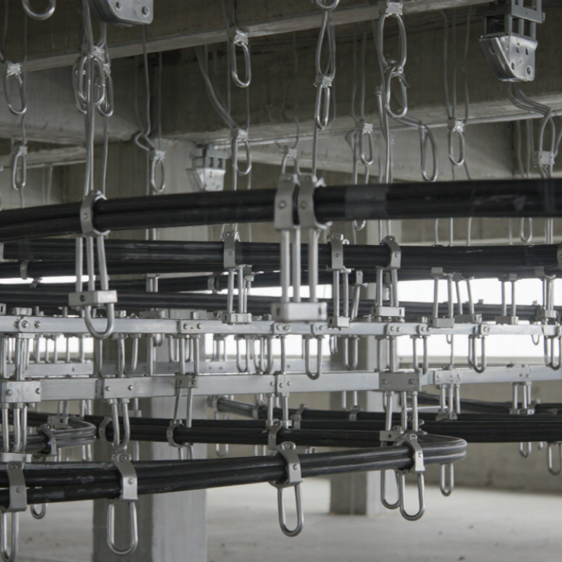
Choosing cable hangers starts with project requirements, not catalog dimensions. Define cable weight, span, routing direction, temperature, moisture, vibration, and maintenance access. A hanger rated for a dry ceiling may fail in a humid plant or crowded data room. It happens.
For vertical runs, select supports that control slipping and preserve the cable’s minimum bend radius. For overhead routes, check the real load, including future cables, water, and accidental impact.
IEC 61537:2023 emphasizes mechanical performance and load testing for cable support systems, so published working-load data deserves careful review. Do not rely on appearance. A thicker hanger is not automatically stronger.
Field inspections often find sharp edges, uneven spacing, and supports fixed to weak surfaces. These details can damage jackets or transfer stress into terminations.
NFPA’s Home Structure Fires Involving Electrical Distribution and Lighting Equipment report estimated 32,410 such fires annually in the United States from 2015 to 2019, with 470 deaths and 1,100 injuries. Cable hangers are not the only cause, but poor support can worsen mechanical damage and inspection risks.
In corrosive areas, compare material compatibility with the environment, then verify fasteners and separation distances. I would also allow spare capacity, although excessive spacing can increase cost and deflection. The calculation may need revision after installation. That is normal.
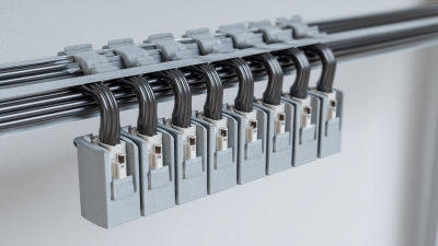
Cable hanger selection depends on cable type, load, routing, and the installation environment. J-hooks suit low-voltage data, security, and communications cables. They provide quick access and reduce tight bends. Ring hangers work well for small bundles in ceilings and vertical drops. Cable trays are better for heavier, denser routes requiring future expansion. Conduit hangers provide stronger mechanical protection in workshops, parking areas, and exposed locations.
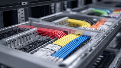
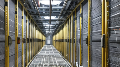
This choice matters as cable volumes increase. The International Energy Agency’s Electricity 2024 report projects data-centre electricity use could exceed 1,000 TWh by 2026, compared with about 460 TWh in 2022. Higher equipment density means more cabling, more heat, and greater support loads. In server rooms, use adjustable trapeze supports or tray systems with documented load ratings. Keep power and communication cables separated where project standards require it. Small details matter.
The Uptime Institute’s 2023 Global Data Center Survey reported that 60% of respondents experienced an outage during the previous three years. Poor cable support may not cause every failure, but sagging routes complicate inspection and maintenance. Select corrosion-resistant hangers for humid areas, fire-rated components where specified, and seismic bracing in higher-risk regions. Check spacing against the manufacturer’s tested capacity and applicable electrical standards. A common mistake is choosing by cable diameter alone. I would also review future capacity, because an empty hanger today may be fully loaded next year.
Cable hanger selection depends on cable quantity, installation environment, movement, and required accessibility. The chart uses a practical 0–5 suitability index, where 5 indicates a highly typical application and 0 indicates that the hanger type is generally unsuitable.
Use J-hooks for accessible data and communication cables, loop hangers for lightweight single cables, saddle clamps for individually secured power cables, cable trays for large grouped cable runs, and messenger clamps for overhead outdoor or suspended installations. Always verify load ratings, cable diameter, spacing, and local electrical requirements before installation.
Material selection affects safety, service life, and maintenance. Galvanized steel suits dry indoor spaces and moderate corrosion exposure. Stainless steel performs better near salt spray, chemicals, or persistent humidity. Polymer hangers resist corrosion, but heat and ultraviolet exposure can reduce their strength. Check the manufacturer’s temperature range carefully. A cheap hanger can become brittle above a warm ceiling.
Load capacity needs practical calculation. Add cable weight, spacing, accessories, and possible installation forces. Then apply the project’s safety factor. Use the rated working load, not the breaking load.
The National Fire Protection Association reported about 32,000 U.S. home fires involving electrical distribution and lighting equipment each year from 2015 to 2019.
Poor support is not always the cause, but loose or damaged systems increase inspection concerns. Never let a hanger crush insulation or create a sharp bend.
Durability also depends on the environment. Look for tested resistance against corrosion, vibration, heat, and ultraviolet exposure. IEC 61537 provides testing principles for cable support systems, including mechanical-load performance.
OSHA guidance also stresses secure support and protection from physical damage. I have seen installations that looked tidy but used undersized supports. That mistake is easy to repeat.
Recheck spacing after adding cables, because future expansion often changes the original load assumptions. Keep inspection records, especially where access is difficult.
How to Choose the Right Cable Hangers for Your Project?
Cable hanger selection begins with the installation environment, cable weight, and support structure. Threaded rods suit suspended ceilings, while beam clamps work well on exposed steel. Surface-mounted hangers can keep wiring close to concrete walls. Always check the hanger’s load rating against the combined cable weight, not one cable alone.
Spacing should follow the cable type, hanger instructions, and local electrical codes. Many projects use intervals between 1.2 and 1.5 meters, but this is not a universal rule. Heavy bundles may need closer supports. Long, unsupported sections can sag visibly and place stress on connectors. Keep cables away from sharp edges, hot surfaces, and moving equipment. Respect the minimum bending radius.
Safety depends on more than strong hardware. Use corrosion-resistant hangers in damp areas and fire-rated supports where required. Do not hang cables from pipes, sprinkler lines, or unrelated building services. Leave enough space for inspection and future maintenance. A crowded tray is difficult to repair. It also hides damage.
I once saw a neat installation fail because the support spacing ignored a heavier cable added later. The original plan looked acceptable. It was not. Inspect each fixing point for movement, loose fasteners, and overloaded supports before energizing the system. A second review is often worthwhile.
| Cable Hanger Type | Recommended Installation Method | Suitable Cable Applications | Typical Spacing Guidance | Key Load or Capacity Consideration | Important Safety Requirements |
|---|---|---|---|---|---|
| J-Hook Cable Hanger | Fasten to structural steel, threaded rod, or approved building support using the specified screw, clamp, or beam attachment. Keep the hook aligned with the cable route. | Low-voltage data, telecommunications, security, audio/video, and control cables. | Common planning range: 1.2–1.5 m (4–5 ft). Reduce spacing near bends, transitions, and heavy cable bundles. | Select a hanger with a rated working load above the calculated cable bundle weight, including future expansion allowance. | Do not suspend from ceiling tiles or grid wires. Avoid overcrowding and maintain the minimum bend radius specified by each cable manufacturer. |
| Bridle Ring | Install with an approved eye screw, beam clamp, or threaded attachment. Use a protective sleeve or smooth ring surface where cable abrasion is possible. | Small communications, alarm, access-control, and control cable bundles. | Typically 0.9–1.2 m (3–4 ft), depending on cable stiffness, bundle size, and route orientation. | Best suited to light cable loads. Confirm ring diameter so cables are supported without compression. | Use a closed or suitably retained support where vibration, vertical routing, or accidental displacement could allow cables to fall out. |
| Cable Basket or Tray Hanger | Suspend from threaded rods, trapeze supports, or manufacturer-approved brackets attached to the building structure. Level the support before loading cables. | Organized routes containing multiple communications, control, or power cables where separation and future access are needed. | Often 1.5–2.4 m (5–8 ft), but the final spacing must follow the tray or basket load table and the project structural design. | Check total cable weight, concentrated loads, span limits, support deflection, and the strength of the attachment to the structure. | Maintain required separation between power and communication circuits. Bond and ground metallic tray systems where required by the applicable electrical code. |
| Trapeze Cable Support | Install a steel channel or equivalent cross-member on threaded rods connected to structural framing. Use retaining hardware where cables may move or roll off. | Heavy or numerous cable bundles, mixed cable routes, and installations requiring a wide support platform. | Common range: 1.5–2.4 m (5–8 ft), subject to channel size, rod diameter, span, and calculated load. | Design for the combined dead load of cables, support steel, accessories, and any foreseeable future additions. | Do not use undersized rods or unapproved fasteners. Keep supports clear of access panels, sprinklers, lighting, and mechanical equipment. |
| Cable Cleat | Bolt or screw directly to a rigid surface, cable ladder, or tray using the specified hardware. Install around the cable group without damaging insulation. | Single-core or multicore power cables requiring restraint against movement, especially in vertical, industrial, or high-fault-current installations. | Spacing is application-specific; typical design ranges are approximately 0.3–1.5 m (1–5 ft), based on fault current, cable arrangement, and cleat rating. | Verify short-circuit withstand rating, cable diameter range, installation formation, and the maximum permitted cleat spacing. | Use nonmagnetic cleats or suitable installation methods for single-core AC cables where magnetic heating could occur. Never overtighten onto the cable jacket. |
| Hook-and-Loop Cable Strap | Wrap loosely around the cable bundle and attach to a dedicated hanger, rack, tray, or support system. Keep the fastener accessible for future servicing. | Data, fiber-optic, patch, and other sensitive cables that may be damaged by excessive compression. | Use at approximately 0.3–0.6 m (1–2 ft) intervals on horizontal runs, or as needed to prevent sagging and cable movement. | Straps provide bundling rather than primary structural support; pair them with rated hangers or tray systems. | Avoid tight plastic ties on data and fiber cables. Do not exceed the manufacturer’s bend radius or crush-force limits. |
| Vertical Riser Support | Use approved riser clamps, cleats, brackets, or rack supports fixed to the building structure. Provide support at floor penetrations and route changes. | Vertical power, communications, fire-alarm, and control cable runs between floors or equipment levels. | Follow the cable and support manufacturer’s vertical-load instructions; add supports at terminations, bends, and penetrations. | Calculate the entire vertical cable weight and divide it among supports. Confirm allowable pull tension and termination loading. | Firestop every rated penetration with a compatible tested system. Protect cables from sharp edges and provide identification at each level. |
| Outdoor or Corrosion-Resistant Hanger | Attach to corrosion-resistant structural supports using compatible fasteners. Provide drainage and avoid locations where water can collect around the cable. | Exterior communications, security, photovoltaic, control, and industrial cable routes. | Usually 0.9–1.5 m (3–5 ft), with closer spacing in areas exposed to wind, vibration, ice, or frequent temperature changes. | Account for cable weight, wind loading, ice loading, thermal movement, ultraviolet exposure, and support corrosion. | Use materials compatible with the environment. Seal building entries, maintain weatherproofing, and use outdoor-rated cable and fittings. |
Selecting cable hangers is not only a matter of matching diameter. The hanger must support the cable bundle without crushing insulation or creating sharp pressure points. Check the working load, safety margin, hanger spacing, and installation direction against the project drawings. Outdoor routes also need suitable resistance to moisture, heat, and corrosion. Ask for test data, material details, and traceable inspection records before approving a product.
Sourcing mistakes often begin with incomplete measurements. A buyer may quote the cable’s outer diameter, but ignore expansion, protective sleeves, or future additions. Measure the real bundle at its widest point. Request samples and test them with the actual cable weight. A small trial section can reveal slipping, twisting, or difficult access that a catalog photo cannot show. It is worth checking.
I once accepted a low-cost hanger after comparing only unit prices. The shipment arrived quickly, but its spacing requirements increased labor and support steel costs. That error changed my checklist. I now compare total installed cost, production lead time, packaging, replacement quantities, and inspection procedures. Confirm thread sizes and mounting hardware too. They are easy to overlook. Written requirements should include tolerances, finish, quantity, delivery location, and acceptance criteria. Without these details, different suppliers may quote different products under the same description.
Fill out the form below and our team will get back to you ASAP.
Snake Tray® is Green and Proudly Powered by the Sun! Snake Tray is committed to designing and manufacturing products that have many green benefits. Our products are made of recycled goods, minimize material waste, are energy efficient, use less non-renewable resources and nest together read more…
Snake Tray® 291 Skip Lane, Bay Shore NY 11706 | PHONE: 631-674-0004 | FAX: 631-674-0010 | www.bakoselectric.com | LEGAL | MADE IN USA
© 2025 SnakeTray. All rights reserved
Fill out the form below to download your document.