Why Is an Inverter Inductor Needed?
An inverter turns direct current into alternating current, but its output is not always a smooth waveform. Fast switching devices create current ripple and electrical noise. An Inverter Inductor helps manage these effects by resisting rapid changes in current and storing energy in its magnetic field. In a typical system, it works with capacitors and control circuitry to shape the output for a motor, grid connection, or other load. The result depends on the full design, not one component alone.
Look at the hardware. A coil of copper wire around a magnetic core may seem simple, yet its rating, core material, winding resistance, and cooling all matter. Too little inductance can leave excessive ripple; too much can affect response, size, and cost. Engineers therefore consider switching frequency, expected current, temperature rise, and the inverter’s operating range when selecting a part. They also check saturation current, since a core pushed too hard may lose inductance and overheat. Small details count.
This article explains why the inductor is needed, where it sits in common inverter circuits, and what changes when its value or construction changes. It also distinguishes filtering from energy storage, two roles that are easy to blur. Real installations vary, and a design that works well on a bench may behave differently under a changing load. That is worth remembering. The inductor is not a cure-all, and its presence alone does not guarantee clean power. Understanding its role makes troubleshooting more practical and component choices less like guesswork.
What an Inverter Inductor Is and Where It Fits
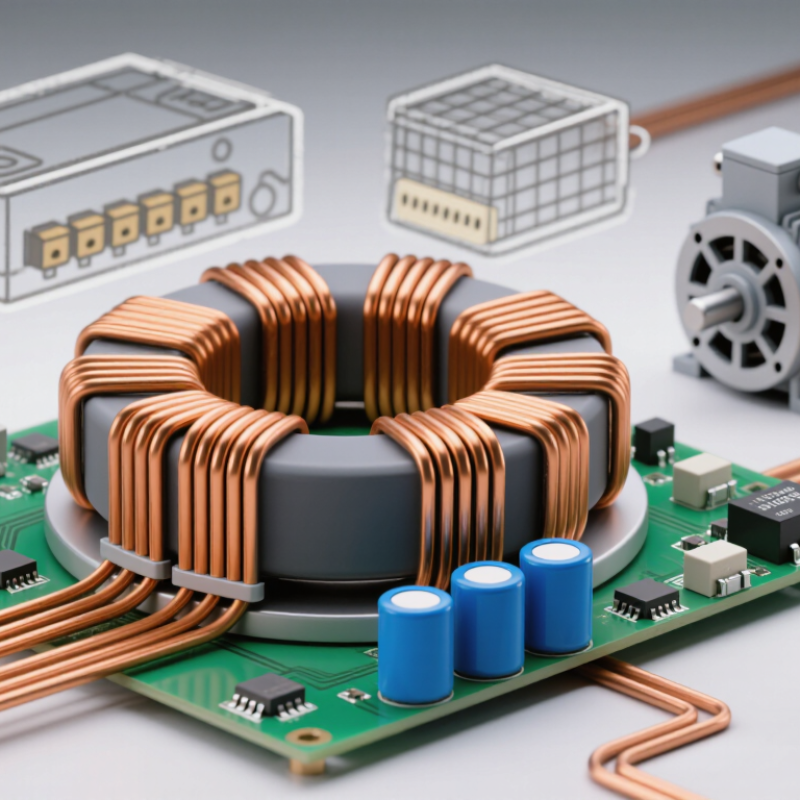
An inverter inductor is a coil of insulated wire around a magnetic core. It stores energy in a magnetic field and resists sudden changes in current. In a typical solar inverter, it sits between the switching bridge and the AC output, helping smooth the pulsing current before it reaches the grid. Some designs also use inductors on the DC side, such as in a boost-converter stage. Placement depends on the circuit.
The need is growing with inverter use. IRENA’s Renewable Capacity Statistics 2024 reports that the world added 473 GW of renewable power capacity in 2023. Much of that capacity connects through power electronics, where current quality and heat matter. A correctly selected inductor limits ripple and can reduce electrical noise. Its winding resistance and magnetic core also create losses, though, and a small component can become a hot spot under sustained load. The details matter.
In practice, engineers check inductance, current rating, core saturation, temperature rise, and switching frequency together. A saturated core may lose inductance, allowing current peaks to climb. The inductor may also vibrate slightly as magnetic forces change; that sound is easy to miss during bench testing. Inductor choice is a compromise between size, efficiency, cost, and thermal headroom—not a part that can be selected by inductance alone.
| Why Is an Inverter Inductor Needed? - What an Inverter Inductor Is and Where It Fits |
| Inverter configuration | Where the inductor fits | Main purpose | Practical design consideration |
| Grid-connected inverter | Between the inverter’s AC switching stage and the grid, often as part of an L or LCL filter | Reduces switching-current ripple and helps limit high-frequency harmonics in the current supplied to the grid | An LCL filter uses two inductive sections and a capacitor; damping is commonly considered to control its resonance. |
| Motor-drive inverter | May be fitted on the DC link or between the inverter output and the motor | A DC-link choke can reduce current ripple, while an output reactor can help reduce voltage stress and cable-related effects | Whether an additional inductor is needed depends on the drive design, motor cable length, switching behavior, and application requirements. |
| Standalone voltage-source inverter | At the AC output, typically in series with the load or within an output LC filter | Helps smooth the pulse-width-modulated output into a waveform suitable for the connected load | The filter must be designed for the inverter’s switching frequency, output frequency, load range, and allowable voltage drop. |
| Inverter with a DC-DC conversion stage | Inside the DC-DC stage, before the DC bus feeding the inverter bridge | Stores and transfers energy during switching, supporting voltage conversion and helping control input or output current | Inductance, current rating, core material, and winding losses are selected for the converter topology and operating conditions. |
| Inverter without a separate external inductor | Inductance may be integrated into the filter, transformer, magnetic components, or system wiring | Provides the inductive behavior needed for energy transfer or ripple control without necessarily using a standalone component | Not every inverter has a visibly separate “inverter inductor”; the required inductance depends on the circuit topology and system design. |
How an Inductor Shapes Current in an Inverter
Why Is an Inverter Inductor Needed?
In an inverter, voltage often changes in rapid pulses as switches turn on and off. The inductor helps shape the resulting current. Because current through a coil cannot change instantly, the inductor softens each pulse and limits sharp rises and falls. In simple terms, it gives current a smoother path.
Look at a current trace on an oscilloscope: the switching ripple appears as small, fast wiggles. An inductor can reduce those wiggles before current reaches a motor, transformer, or grid connection. Less ripple can mean lower electrical noise and less stress on connected components. Not perfectly smooth, though. The result depends on the switching frequency, load, and surrounding filter components.
The value and construction matter. A small inductor may allow excessive ripple, while a larger one can add weight, cost, and losses. Its core can also saturate if current exceeds its design range, reducing its ability to control current. Heat is another clue worth checking; a warm component may be carrying more loss than expected. Choosing an inductor is therefore a balance, not a simple matter of making it as large as possible. Even careful designs can behave differently under changing loads, so measurements in the finished system still matter.
How It Reduces Ripple and Electromagnetic Interference
An inverter inductor resists rapid changes in current. During each switching cycle, it stores energy in its magnetic field and releases it between pulses. This softens sharp changes in output current. Less ripple. In a motor drive, steadier phase current can reduce audible whine and heating in connected components. The result depends on the circuit, load, and switching frequency; an inductor alone cannot make a rough waveform clean.
Smoother current also helps limit electromagnetic interference. Fast current transitions can create voltage spikes and noise that travel along cables or couple into nearby circuits. A suitably selected inductor slows those transitions, while careful wiring and filtering help keep remaining noise from spreading. Its physical location matters. Long leads between the inductor and switching devices can weaken the benefit. A saturated core may also let ripple rise sharply. A practical check is to measure ripple at the intended load, not only under light bench conditions. Measurements can surprise. Core losses, temperature, and component tolerances complicate neat calculations, so selection often calls for testing and revision.
How It Supports Stable, Efficient Power Conversion
An inverter inductor helps turn rapid electronic switching into usable, steady power. It stores energy in a magnetic field, then releases it between switching pulses. This smooths current, reduces ripple, and helps limit electrical noise. Small part. Without suitable inductance, current can fluctuate sharply, stressing switches and heating nearby components. The result may be less efficient conversion, not just a messier waveform.
The scale matters. NREL’s 2024 Annual Technology Baseline uses an inverter-efficiency assumption of about 98% for utility-scale solar modeling. That leaves little room for avoidable losses. Sandia National Laboratories’ report, Performance Model for Grid-Connected Photovoltaic Inverters, models efficiency across different power levels and input voltages. That is a useful reminder: performance changes with operating conditions. An inductor must be sized for expected current, switching frequency, and temperature; too small, and it may saturate, while an oversized part can add cost and resistance. At a workbench, engineers check temperature rise and current ripple under changing loads, not only at one ideal operating point. I would not treat the inductor as a minor detail. It helps make stable conversion possible, but its design still involves trade-offs.
Key Factors in Choosing an Inverter Inductor
Why Is an Inverter Inductor Needed?
Key Factors in Choosing an Inverter Inductor
An inverter inductor helps smooth current and limit ripple as switching devices turn on and off. Choosing one involves more than matching an inductance value on a datasheet. The wrong part can run hot, saturate, or add avoidable losses.
Start with the inverter’s input voltage, switching frequency, and expected load range. Too little inductance may allow excessive ripple current. Too much can slow the response when the load changes. Check saturation current against peak operating current, with enough margin for brief surges. A margin that looks generous on paper may shrink in a warm enclosure.
Heat matters. Core material and construction affect losses at the chosen frequency, while winding resistance contributes to copper heating. Check the manufacturer’s temperature-rise data, then consider airflow and nearby heat sources. A compact inductor beside a warm power device may need more thermal headroom than its rating suggests.
Finally, consider physical size, mounting, and winding layout. Long connections can add parasitic effects, so placement near the switching stage is often useful. If possible, measure ripple and temperature in the actual design; bench results may differ from calculations. It is tempting to choose the smallest part that meets the electrical figures, but that tradeoff deserves a second look.
Why Is an Inverter Inductor Needed? — Key Factors in Choosing One
An inverter inductor stores energy and limits current ripple. The chart shows how estimated ripple changes with inductance in a simplified example using a 100 V inductor voltage and a 20 kHz switching frequency.
How to use this: The estimate uses ΔI = VL / (L × fs), assuming a constant inductor voltage over one switching period. Actual inverter ripple depends on the topology, modulation, and operating point. When selecting an inductor, check the required ripple limit, peak and RMS current, saturation-current margin, core and copper losses at the switching frequency, temperature rise, and size.