Choosing the right transformer begins with understanding how its core shapes performance, efficiency, size, and cost. Transformer Core Types are not merely construction labels. They influence magnetic flux, operating frequency, heat generation, noise, insulation needs, and long-term reliability. A small ferrite core may fit inside a compact switching power supply, while a laminated steel core can support dependable low-frequency power conversion.
This guide examines common core designs, including air-core, iron-core, ferrite, toroidal, laminated, and amorphous-metal options. Each type suits a different engineering environment. Air-core transformers can reduce saturation concerns in high-frequency applications. Ferrite cores help limit losses at switching frequencies. Laminated steel cores remain practical for many 50 Hz or 60 Hz systems. A toroidal core often reduces leakage flux, but winding it accurately can require more labor and specialized equipment.
Details matter.
Real-world selection involves more than reading a datasheet. Engineers compare core material, magnetic flux density, temperature rise, winding space, insulation class, and expected load cycles. A transformer that runs quietly on a test bench may become noticeably warm inside a sealed enclosure. That observation is easy to overlook. It can affect service life.
Reliable evaluation also includes reviewing manufacturer data, recognized safety standards, and verified measurements. No single core type is universally best. Design priorities can conflict, and simplified comparisons may hide important limitations. Understanding those trade-offs makes transformer selection more deliberate, practical, and technically defensible.
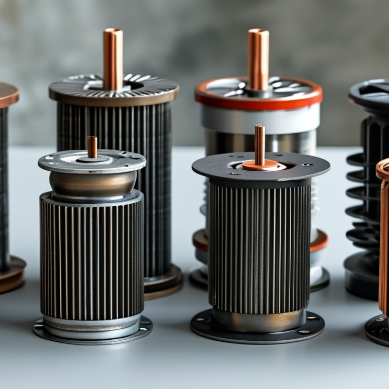
Transformer core types are best understood through two choices: magnetic material and physical construction. Laminated silicon steel cores remain common in power-frequency transformers. Thin insulated sheets reduce eddy-current losses and support dependable operation. Ferrite cores suit high-frequency circuits because their electrical resistance is high. They are light, compact, and effective in switch-mode designs. Amorphous metal cores can reduce no-load losses, although cost and processing limits matter. Nanocrystalline materials offer strong magnetic performance in demanding high-frequency applications. The best material depends on frequency, flux density, temperature, and required efficiency.
Construction changes behavior too. An EI core uses separate E and I laminations, making assembly practical and repair-friendly. A toroidal core forms a closed magnetic path, which usually reduces leakage flux and audible hum. Cores with air gaps are common in inductors and energy-storing transformers. The gap controls inductance and helps prevent saturation. A C-core or shell-style structure can improve winding placement and shielding. Still, geometry alone does not guarantee better results. Poor winding tension, uneven insulation, or sharp lamination edges can create losses and reliability problems. In real testing, temperature rise often reveals weaknesses that calculations miss.
Tips: Match the core to operating frequency, not just power rating. Check saturation flux, loss curves, insulation limits, and tolerances. Measure temperature under realistic load conditions. Leave room for cooling. Small details matter. I have found that a slightly larger core often gives calmer thermal behavior, but it may increase cost and winding length. Review the design after testing; early estimates are rarely perfect.
Transformer core shape directly affects efficiency, heat, noise, and physical size. The magnetic path is the key detail. A shorter, more continuous path usually reduces losses and improves energy transfer.
Laminated E-I cores are practical and easy to manufacture. Their layered steel structure helps limit eddy currents. However, the joints can increase magnetic reluctance and audible vibration.
Toroidal cores provide a nearly continuous magnetic path. They often reduce leakage flux and hum, while offering compact dimensions. Installation can be less convenient because winding the coil requires careful handling.
C-cores use shaped laminations with a small joint. They balance low losses, mechanical strength, and flexible assembly. That balance is useful in demanding equipment. Still, one design rarely wins everywhere.
Tips: Match the core shape to frequency, power, temperature, and available space. Check the magnetic flux density before choosing dimensions. A core running too close to saturation may overheat quickly. Measure vibration and temperature during real-load testing, not only during calculations. Small design errors can become expensive later.
In practical testing, I have found that geometry changes feel minor until the transformer operates continuously. A slightly larger core may lower temperature and extend insulation life. Yet, increasing size can add weight and material cost. Designers should question every compromise. Calculations guide the choice, but measured results remain essential. Some unexpected noise may come from clamping pressure, not the core shape itself. That detail is easy to miss.
Laminated transformer cores remain practical because thin steel sheets limit eddy-current losses. The most familiar design is the EI core. It uses stacked E-shaped and I-shaped laminations, creating a clear magnetic path around the windings. EI cores suit control transformers, chargers, and small industrial power supplies. They are inexpensive and easy to assemble. The air gap at the joint, however, can increase audible hum and magnetizing current.
UI cores use two U-shaped sections with separate I laminations or matching limbs. This layout supports larger windings and can simplify mechanical mounting. Engineers often select it for industrial control equipment and medium-power isolation transformers. A toroidal laminated core uses a continuous wound steel strip. Its closed magnetic path usually reduces leakage flux and noise. It fits audio equipment, medical supplies, and compact instrumentation, where space matters.
The application choice is not purely about efficiency. IEA’s Electricity 2024 report forecasts global electricity demand growth of about 3.4% annually from 2024 to 2026. That pressure makes no-load losses more important across thousands of energized transformers. Grain-oriented electrical steel, tighter joints, and careful clamping can improve performance, but manufacturing tolerances still matter. Small gaps become costly at scale. DOE efficiency analyses also treat core loss as a lifetime operating concern, not merely a factory test result. Engineers sometimes overvalue a compact toroid and overlook thermal access. That is a real design mistake.
Common laminated core designs and their representative application frequency ranges
The ranges show common design-use bands rather than absolute material limits. EI, UI, and EE laminated electrical-steel cores are widely used in mains-frequency power, control, and low-frequency industrial transformers. LL cores are frequently selected for audio and signal transformers because their construction can support wider low-frequency response. Actual limits depend on lamination thickness, steel grade, flux density, insulation, winding design, and cooling.
Interleaved E-shaped and I-shaped laminations; common in mains transformers, adapters, and control transformers.
U-shaped and I-shaped laminations; useful for power transformers where a large winding window and robust assembly are needed.
Two E-shaped stacks form a compact magnetic circuit; used in compact power, control, and signal transformer designs.
L-shaped laminations create a low-profile structure; commonly associated with audio, signal, and specialized low-frequency transformers.
Toroidal transformer cores use a continuous ring of magnetic material. Their closed path reduces leakage flux and supports compact, quiet designs. In practical testing, toroidal units often show lower audible hum than laminated rectangular cores. That matters in medical rooms, audio equipment, and precision control cabinets. Winding remains difficult. Uneven tension can increase losses.
The global grid is entering a replacement cycle. The International Energy Agency’s Electricity Grids and Secure Energy Transitions report estimates annual grid investment must exceed 600 billion dollars by 2030. This pressure favors efficient, space-saving core structures. Toroidal cores suit low-profile assemblies, while split-core designs simplify current measurement around existing conductors. Planar cores offer very short magnetic paths for high-frequency converters. Nanocrystalline and amorphous materials can reduce core losses, although material cost and manufacturing complexity remain obstacles.
Efficiency claims require operating conditions, not attractive catalog figures. The U.S. Department of Energy’s 2024 distribution-transformer rule projects about 3.6 quadrillion British thermal units in energy savings over thirty years. Core geometry contributes, but conductor resistance, temperature, insulation, and load profile also decide real performance. A specialized core is not automatically better. Engineers should compare no-load loss, sound level, thermal rise, repair access, and lifecycle cost. My own caution is simple: compactness can hide maintenance problems. A smaller transformer may still need more careful installation.
What Are the Different Transformer Core Types?
Choosing a Transformer Core Type for Specific Requirements
Transformer core selection starts with frequency, power level, temperature, and acceptable losses. Laminated silicon-steel cores suit 50 or 60 Hz power transformers. They offer predictable performance, strong mechanical durability, and reasonable cost. However, they can become bulky and produce noticeable audible hum.
Ferrite cores fit high-frequency switching applications because their high electrical resistance limits eddy-current losses. They work well in compact converters, though their lower saturation flux density demands careful magnetic design. Nanocrystalline and amorphous cores can reduce core losses, especially during light-load operation. This matters as grid equipment operates more frequently under variable demand. The International Energy Agency’s Electricity 2024 report says annual grid investment must exceed 600 billion dollars by 2030. Efficiency cannot remain an afterthought. Powdered-iron cores suit inductive energy storage better than many isolation transformers. The choice is not always obvious.
Tips: Define the operating frequency before comparing materials. Check core loss at the actual temperature, not only at room temperature. Measure magnetizing current and acoustic noise in a finished enclosure. A smaller core may save space, but it can increase heating and saturation risk. In my design reviews, datasheet values often looked impressive until real airflow changed everything. Leave margin for tolerances, aging, and imperfect assembly.
| Core Type | Typical Core Material | Common Frequency Range | Main Characteristics | Advantages | Limitations | Suitable Applications | Best Selection Priority |
|---|---|---|---|---|---|---|---|
| Laminated EI Core | Silicon steel laminations | Approximately 50–400 Hz | E-shaped and I-shaped laminations assembled around one or two coils. | Low cost, easy to manufacture, simple coil winding, and widely available in many sizes. | Higher audible noise, larger leakage flux, and greater size than high-frequency ferrite designs. | Mains-frequency power transformers, control transformers, isolation transformers, and audio equipment. | Economy, serviceability, and compatibility with line-frequency operation. |
| Laminated UI Core | Silicon steel laminations | Approximately 50–400 Hz | U-shaped and I-shaped laminations form a magnetic circuit around the windings. | Can provide a long winding window and useful mechanical flexibility for larger transformers. | Assembly may require careful clamping; magnetic gaps and leakage depend strongly on construction. | Power supplies, welding transformers, industrial control equipment, and audio transformers. | Winding space, mechanical layout, and required power capacity. |
| Toroidal Core | Grain-oriented silicon steel, ferrite, powder iron, or nanocrystalline material | About 50 Hz to several hundred kHz, depending on material | A continuous ring-shaped magnetic path with windings distributed around the circumference. | Low leakage flux, high magnetic efficiency, compact shape, and generally low acoustic radiation. | Winding can be more difficult and costly; mounting and thermal management require careful design. | Low-noise audio equipment, medical devices, instrumentation, and compact power supplies. | Low stray field, compact packaging, and low audible noise. |
| C-Core | Grain-oriented silicon steel or amorphous alloy | Approximately 50 Hz to several kHz | Two C-shaped sections create a closed magnetic path, usually with a controlled joint. | Low core loss, good magnetic efficiency, accessible windings, and relatively low leakage when assembled correctly. | Core joints require accurate finishing and clamping; construction is usually more specialized than EI designs. | High-quality audio transformers, power transformers, instrumentation, and low-loss magnetic assemblies. | Low loss, controlled air gap, and efficient winding access. |
| R-Core | Specially processed silicon steel, commonly formed into a continuous round magnetic path | Approximately 50–400 Hz | A near-seamless core geometry with separate primary and secondary bobbins or windings. | Low vibration, low audible noise, low no-load current, and good isolation between windings. | Specialized manufacturing, higher cost, and less flexibility in custom mechanical designs. | Precision instruments, medical electronics, audio equipment, and noise-sensitive systems. | Acoustic performance, low standby loss, and electrical isolation. |
| Ferrite E-Core | Manganese-zinc or nickel-zinc ferrite | Approximately 20 kHz–1 MHz, material dependent | Two E-shaped halves form a magnetic circuit around a bobbin-mounted winding. | High electrical resistivity, low eddy-current loss at high frequency, low cost, and easy automated assembly. | Lower saturation flux density than steel; core loss and temperature rise increase if frequency or flux is excessive. | Switch-mode power supplies, gate-drive transformers, flyback converters, and high-frequency isolation transformers. | Switching frequency, power density, insulation system, and allowable temperature rise. |
| Ferrite EE/ETD Core | Manganese-zinc ferrite | Approximately 20 kHz–500 kHz | Optimized center-leg and winding-window geometry for compact high-frequency transformers. | Good power-to-volume ratio, standardized bobbins, effective heat removal, and predictable winding construction. | Requires careful control of flux density, winding losses, creepage, clearance, and electromagnetic interference. | AC-DC adapters, telecom power supplies, server power systems, and DC-DC converters. | Power density, thermal design, winding window utilization, and regulatory insulation requirements. |
| Planar Ferrite Core | High-frequency ferrite | Approximately 100 kHz–2 MHz, design dependent | Flat core and low-profile windings, often implemented with a printed circuit board or stamped conductor. | Very low profile, repeatable construction, short winding length, and excellent suitability for automated production. | Limited winding thickness, higher PCB and conductor costs, and increased sensitivity to layout and parasitic effects. | High-density telecommunications power, computing equipment, automotive electronics, and compact converters. | Height restriction, repeatability, high-frequency efficiency, and production volume. |
| Powdered-Iron Core | Iron powder with a distributed insulating binder | Approximately 10 kHz–500 kHz, material dependent | Distributed air gap is inherent throughout the magnetic material. | High DC-bias tolerance, useful energy storage capability, and no discrete gap requiring mechanical adjustment. | Higher core loss than many ferrites at elevated frequency and comparatively lower permeability. | Power inductors, energy-storage chokes, output filters, and some high-frequency transformers. | DC-bias capability, stored energy, and controlled inductance under load. |
| Nanocrystalline Core | Nanocrystalline iron-based alloy | Approximately 1 kHz–300 kHz, design dependent | Very fine crystalline structure provides high permeability and low magnetic loss over a broad operating range. | High saturation flux density, strong common-mode attenuation, compact size, and excellent permeability. | Higher material cost, more demanding processing, and possible sensitivity to mechanical stress. | Common-mode chokes, current transformers, high-performance filters, and high-efficiency power converters. | Magnetic performance, electromagnetic-noise suppression, compactness, and efficiency. |
Fill out the form below and our team will get back to you ASAP.
Snake Tray® is Green and Proudly Powered by the Sun! Snake Tray is committed to designing and manufacturing products that have many green benefits. Our products are made of recycled goods, minimize material waste, are energy efficient, use less non-renewable resources and nest together read more…
Snake Tray® 291 Skip Lane, Bay Shore NY 11706 | PHONE: 631-674-0004 | FAX: 631-674-0010 | www.bakoselectric.com | LEGAL | MADE IN USA
© 2025 SnakeTray. All rights reserved
Fill out the form below to download your document.