What Is a Wall Mounted Battery Harness and How Does It Work?
A Wall Mounted Battery Harness is a structured connection system that supports batteries installed against a wall. It links the battery pack with an inverter, charger, monitoring device, or backup circuit. In practical terms, it combines cables, connectors, protective fittings, and mounting support in one organized arrangement. The goal is simple: deliver stored electrical energy safely and consistently.
When the battery supplies power, current travels through the harness toward the connected equipment. Built-in fuses, breakers, terminals, and communication wires may help control faults and share operating information. The exact design depends on battery chemistry, voltage, current capacity, and installation conditions. A residential lithium battery system may use different components from an industrial backup unit. Details matter.
A clean installation is easier to inspect. It can also reduce loose cables, sharp bends, heat buildup, and accidental contact. However, a harness does not make an unsafe battery safe. It cannot replace correct sizing, ventilation, grounding, or professional commissioning. That point is easy to overlook. Installation manuals and manufacturer specifications should guide every connection. A qualified technician can verify polarity, torque, insulation, and protective-device ratings before energizing the system. Even experienced installers can miss a small warning label or underestimate heat near a wall. This guide explains how a Wall Mounted Battery Harness works, what components it contains, and which practical checks support reliable operation. Some designs appear similar, but their electrical limits may differ greatly. Careful inspection remains essential.
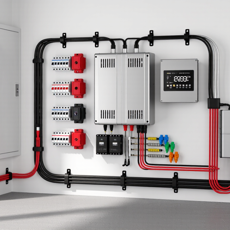
Wall-Mounted Battery Harness Definition: 48 V DC Wiring and Mounting Interface
A wall-mounted battery harness is the wiring and mounting interface connecting a 48 V DC battery to its equipment. It is more than a cable bundle. The assembly normally includes positive and negative conductors, overcurrent protection, a disconnect, communication wiring, and grounding provisions. The mounting plate transfers battery weight into wall framing, while cable glands protect insulation from sharp edges. A loose gland can become a serious failure point.
In a 48 V system, “48 V” describes nominal voltage, not the maximum reading. A fully charged battery may exceed 50 V DC, depending on its chemistry and control system. That difference affects insulation, connector ratings, clearance, and service procedures. The IEA’s 2024 Batteries and Secure Energy Transitions report projects global battery storage capacity will increase sixfold by 2030, reaching 1,200 GW. Modular wall interfaces will matter as installations multiply.
Good field practice keeps power and communication cables separated where practical. Technicians should verify polarity, torque terminals to the manufacturer’s specification, and test protective devices before energizing the circuit. A torque mark helps later inspection. It is a small detail. The harness should also leave enough service loop for inspection without stressing the connector. I would not treat a tidy harness as proof of safety; hidden compression, poor airflow, or weak wall anchoring can remain. Applicable electrical codes and the battery’s installation instructions must control the final design.
What Is a Wall Mounted Battery Harness and How Does It Work? - Wall-Mounted Battery Harness Definition: 48 V DC Wiring and Mounting Interface
| Data Dimension | Typical Data or Definition | How It Works or Why It Matters |
|---|---|---|
| Primary purpose | Organizes, routes, and terminates the direct-current wiring between a wall-mounted battery system and connected equipment. | It combines electrical conductors, connectors, protective components, and mounting features into an organized interface. |
| Nominal system voltage | 48 V DC nominal; the actual battery voltage varies according to cell chemistry, state of charge, and charging conditions. | The harness must be selected for the battery’s maximum operating voltage, not only its nominal label. |
| Main power conductors | A positive conductor and a negative conductor, commonly made from flexible, fine-stranded copper cable. | The conductors carry charging and discharge current between the battery terminals, protection device, and load or charger. |
| Conductor sizing | Determined by continuous current, peak current, cable length, allowable voltage drop, installation temperature, and insulation rating. | Larger or shorter conductors generally reduce voltage drop and heat generation, but the final size must follow the applicable electrical design rules. |
| Overcurrent protection | A fuse or DC-rated circuit breaker is normally installed close to the battery’s positive terminal. | It helps protect the cable and connected equipment from excessive current caused by short circuits or overloads. |
| Isolation and service disconnect | A manually operated DC disconnect may be included in the harness or installed adjacent to the battery. | It allows technicians to isolate the battery from the system during installation, inspection, or maintenance. |
| Battery-management connections | Low-voltage signal wiring may connect the battery-management system to sensors, displays, chargers, inverters, or other battery units. | These circuits can carry monitoring and control signals, but they do not replace the main power cables. |
| Connector requirements | Connectors must be rated for the system’s DC voltage, maximum current, conductor size, temperature range, and environmental conditions. | Correctly rated connectors help maintain low contact resistance and reduce the risk of overheating or accidental disconnection. |
| Mounting interface | May include a bracket, cable-entry plate, strain-relief points, terminal cover, and defined attachment points on the wall or battery enclosure. | The interface supports the battery and keeps wiring aligned, protected, and accessible for service. |
| Cable routing | Cables are routed with suitable bend radii and secured so that they do not hang from terminals or rub against sharp edges. | Proper routing limits mechanical stress, insulation damage, electromagnetic interference, and accidental short circuits. |
| Polarity identification | Positive and negative conductors should be clearly color-coded, labeled, or otherwise identified at both ends. | Clear identification reduces the risk of reverse-polarity connection and simplifies testing and maintenance. |
| Grounding and bonding | Metallic mounting parts and enclosures may require protective bonding or grounding according to the installation design and local electrical requirements. | Bonding can provide a fault-current path and help keep exposed conductive parts at a safer potential. |
| Environmental protection | The required enclosure and connector protection depends on indoor or outdoor location, moisture, dust, corrosion, and temperature exposure. | Sealing, suitable insulation, and corrosion-resistant hardware help preserve electrical and mechanical performance. |
| Thermal considerations | Cable ampacity and connector temperature rise must be evaluated under the expected load and ambient conditions. | Loose terminals, undersized conductors, and restricted airflow can create localized heating. |
| Installation sequence | Mount the support, route and secure the harness, install protection and disconnect devices, verify polarity, then complete electrical connections with the battery isolated. | A controlled sequence reduces accidental energization, wiring errors, and mechanical damage. |
| Inspection checks | Verify polarity, terminal torque, cable support, insulation condition, fuse or breaker rating, connector engagement, and clearance from heat or sharp edges. | These checks help confirm that the wall-mounted battery interface is electrically sound and mechanically secure before energization. |