7 RF Amplifier Buying Tips for Global Buyers
Choosing an RF Amplifier for international projects involves more than comparing prices or headline output power. The right unit must suit the operating frequency, signal bandwidth, gain, and load conditions of the intended system. Small mismatches can cause weak coverage, excess heat, or distorted signals. Details matter.
This guide presents seven practical buying tips for global buyers. It explains how to read key specifications, assess noise figure and linearity, confirm impedance, and check cooling and power requirements. A datasheet is useful, but it cannot answer every question. Ask suppliers for test conditions, performance curves, and clear documentation. Where possible, compare those details with your actual operating needs rather than relying on a single peak-value claim.
International procurement adds its own considerations. Buyers should confirm available technical support, lead times, warranty terms, and compatibility with local power standards. They should also check that product documentation and required conformity information are suitable for the destination and application. Requirements can differ by market, so verify them with qualified sources before ordering. No shortcut here.
A lower purchase price may look attractive, yet operating costs and replacement delays can change the calculation. Consider the full service life, including installation, maintenance, and access to spare parts. Some specifications still need clarification. That is worth admitting. A careful comparison helps teams ask better questions and choose an RF Amplifier that fits the real application, not merely the sales description.
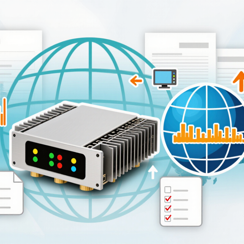
Define the Frequency Range and 50-Ω System Requirements
Start with the frequencies your equipment will actually use, including the lowest and highest operating points. A range listed on a datasheet may look generous, but amplifier gain and output power can vary across it. A wider range is not always safer. Check the performance curves at your target frequencies, not only the headline specifications. Leave practical margin for channel changes or measurement sweeps, but avoid paying for bandwidth you will never use. Small gaps matter.
Confirm that the amplifier is designed for a 50-ohm system at both its input and output. This is the common impedance for many RF instruments, cables, and antennas, but the full signal path still needs checking. A 75-ohm cable or poorly matched adapter can cause reflections, reduce delivered power, and distort measurements. Check the setup twice. Review the specified return loss or VSWR, then verify connections with suitable test equipment when accuracy matters. A mismatch may seem minor at low power, yet become more noticeable across a broad sweep. I would also check the connector type and cable ratings; these details are easy to overlook when comparing amplifier specifications.
Compare Gain and Noise Figure Referenced to 290 K
When comparing RF amplifiers, treat gain and noise figure as a pair, not separate headline numbers. Gain tells you how much a signal rises; noise figure indicates how much signal-to-noise quality the amplifier loses. Check both at your operating frequency. A gain figure measured at 1 GHz may not describe performance near 3 GHz.
Noise figure is commonly referenced to a 290 K source temperature, providing a standard basis for comparison. It does not mean your equipment must operate at exactly 290 K. Read the test conditions carefully, including bandwidth, input matching, and measurement uncertainty. A small difference in reported noise figure may be less meaningful than it looks.
Not always.
For a receiver chain, the first amplifier often has the greatest influence on overall noise performance. Compare its gain with the next stage’s noise figure, then consider the complete cascade. For example, a low-noise amplifier with moderate gain may be preferable to a noisier unit with impressive gain. Check gain flatness across the band, too; a few decibels of variation can complicate downstream calibration. On the bench, cable loss before the amplifier can quietly worsen the result.
I would verify the setup twice—this is an easy detail to overlook.
Check P1dB and OIP3 for Required Linearity and Headroom
For an RF amplifier, P1dB shows where output power begins to compress by 1 dB. Compare that point with the highest expected signal peak, not just average power. A modulated signal can have sharp peaks that exceed its average level. Leave enough headroom to keep those peaks from flattening. That part matters.
OIP3 helps estimate how well an amplifier handles two strong signals without creating excessive third-order intermodulation products. These unwanted products can land near useful channels and reduce receiver or transmitter performance. OIP3 is an extrapolated figure, not a safe operating-power limit. A higher value generally indicates better linearity, but it does not replace checking P1dB. Both figures deserve attention.
Ask suppliers for test conditions, including frequency, supply voltage, temperature, and input spacing used for OIP3 measurements. Results measured under different conditions may not be directly comparable. Then check the full signal chain: cable loss, filters, and downstream stages all affect the available margin. A small spreadsheet helps. It is easy to trust a headline specification too quickly; I would verify critical figures with the intended waveform and operating conditions before selecting a unit.
Match Output Power, Efficiency, Cooling, and Load Conditions
For an RF amplifier, match rated output power to the signal’s real peak demand, not just its average level. Modulated signals need headroom: running near compression can distort peaks and raise heat. Check whether the specification gives saturated power, P1dB, or linear output power; these figures are not interchangeable. A little margin helps, but oversized units may waste energy.
Efficiency depends on operating level. An amplifier’s headline efficiency may apply near peak output, while your system spends much of its time backed off. GSMA’s 2024 Mobile Economy report projects 5.5 billion 5G connections by 2030, highlighting the scale of networks where energy use matters. For a specific design, compare efficiency at your expected output and waveform, then estimate heat from input power minus RF output. Small details matter. A fan cannot fix a poor thermal path from the device to its heatsink.
Check cooling limits and load conditions together. Confirm ambient-temperature ratings, airflow direction, heatsink clearance, and whether power must be reduced at higher temperatures. Then review the specified load impedance and allowable mismatch or VSWR. A long cable, loose connector, or antenna outside its intended band can change the load seen by the amplifier. It is easy to overbuy here. I would rather verify the installed load and duty cycle than trust a generous catalog rating.
7 RF Amplifier Buying Tips for Global Buyers — Match Output Power, Efficiency, Cooling, and Load Conditions
Cooling estimate for a 100 W RF output amplifier at different power-added efficiency (PAE) levels.
Heat dissipation is calculated as RF output power × (1 ÷ PAE − 1). This illustrative estimate assumes 100 W continuous RF output into a matched 50 Ω load; it is not a product specification. Confirm efficiency at your operating frequency, output power, duty cycle, ambient temperature, and specified load VSWR when selecting cooling capacity.
Verify VSWR Tolerance: 2:1 Equals About 9.5-dB Return Loss
When comparing RF amplifiers, check the VSWR tolerance across the full operating band, not just at one test frequency. A 2:1 VSWR corresponds to a reflection coefficient of about 0.33 and roughly 9.5 dB return loss. That means about 11% of incident power is reflected. A useful figure, but not a guarantee that the amplifier can withstand every mismatch continuously.
Ask for test conditions: frequency, input power, temperature, and mismatch phase. A mismatch at the output can stress the final stage, and the worst case may occur at a particular phase angle. Confirm whether the stated tolerance applies during operation or only for brief exposure. Details matter. Check connector type and cable quality too; a loose connection or damaged cable can distort measurements and increase reflected power.
For a deployment spanning different regions, compare the specification with the actual antenna and feed-line setup at each site. Request test data or a written operating limit if the datasheet is unclear. I would not treat 2:1 as a universal pass mark; it may be adequate in one installation and restrictive in another. That distinction is easy to overlook.