What Is a Nozzle Cutting Machine and How Does It Work?
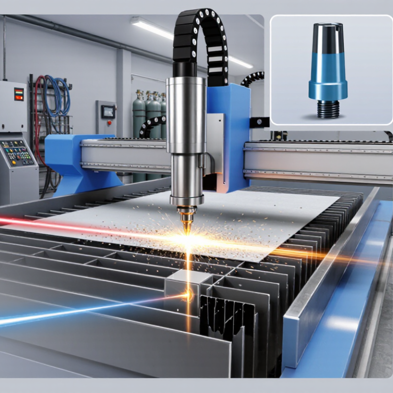
A Nozzle Cutting Machine is a precision system designed to cut metal, plastic, or other industrial materials through a focused energy stream. Depending on the model, it may use laser, plasma, or a high-pressure water jet. The nozzle controls how that energy reaches the workpiece. It shapes the beam or gas flow, maintains cutting distance, and helps remove molten material from the kerf.
Laser-cutting expert Dr. John Powell has described the nozzle as “the last link between the machine and the material.” That simple idea explains its importance. A small nozzle opening can influence cut width, edge quality, heat concentration, and production speed. During operation, the machine follows programmed coordinates while the nozzle moves over a metal sheet. Assist gas may push sparks and vapor away. The cutting head must remain stable, clean, and correctly aligned.
In real workshops, operators often notice problems before software does. A rough edge, excessive slag, or uneven piercing may indicate a damaged nozzle. Wrong gas pressure can create similar symptoms. The answer is not always a higher power setting. Sometimes, the nozzle only needs cleaning or replacement.
This technology appears straightforward. It is not. Material thickness, nozzle diameter, focal position, speed, and gas pressure interact continuously. Even experienced technicians must test settings. A useful introduction should explain both the machine’s working principle and its practical limits, because perfect cuts rarely come from one adjustment alone.
Definition and Main Components of a Nozzle Cutting Machine
A nozzle cutting machine is industrial equipment designed to cut, shape, or open precise nozzle sections in metal, plastic, or composite parts. It is used when manual cutting cannot maintain consistent diameter, depth, or edge quality. In a typical workshop, the machine secures a tube or molded component, positions the cutting tool, and follows programmed measurements. The result is cleaner than a handheld process, although setup errors can still create uneven openings.
The main components include a rigid frame, workholding fixture, cutting head, drive system, and control unit. The fixture prevents movement during cutting. This matters because even slight vibration can damage the nozzle edge. The cutting head may use a rotating blade, milling tool, or abrasive wheel, depending on the material. Servo motors guide movement along controlled axes, while sensors check position and tool travel. Some machines also include coolant or dust extraction systems.
Operation begins with loading the nozzle and entering dimensions into the controller. The machine aligns the part, advances the tool, and removes material in measured passes. Operators should inspect the first piece with gauges or calipers before continuing production. Small deviations can affect flow performance. That detail is often underestimated. Maintenance also requires attention: worn tools, loose fixtures, and incorrect settings can reduce accuracy. No machine removes the need for skilled judgment.
What Is a Nozzle Cutting Machine and How Does It Work? - Definition and Main Components of a Nozzle Cutting Machine
| Category | Component or Parameter | Definition or Typical Specification | Function in the Cutting Process | Important Considerations |
|---|---|---|---|---|
| Machine Definition | ||||
| Definition | Nozzle Cutting Machine | A specialized machine used to cut, profile, drill, or finish industrial nozzles and nozzle openings in metal components. | Produces accurate circular, oval, beveled, or compound openings in items such as pressure-vessel shells, tanks, pipes, and process equipment. | The exact configuration depends on the workpiece size, material, nozzle geometry, and required cutting process. |
| Typical Cutting Methods | Plasma, oxy-fuel, laser, or waterjet cutting | Thermal and non-thermal cutting technologies can be used depending on material thickness and quality requirements. | Separates material along a programmed contour and may create a straight or beveled edge. | Plasma and oxy-fuel are common for heavy steel; laser is suited to precise thinner sections; waterjet avoids heat-affected zones. |
| Main Machine Components | ||||
| Structure | Machine Frame and Bed | A rigid welded or fabricated structure that supports the cutting head, workpiece, rails, and drive system. | Maintains alignment and reduces vibration during cutting. | Structural stiffness directly affects dimensional accuracy and edge quality. |
| Workholding | Workpiece Support and Clamping System | Supports, centers, and secures cylindrical, curved, or flat workpieces during machining. | Prevents movement, rotation, or deformation while the nozzle profile is being cut. | Supports should be positioned to avoid interference with the cutting path and should accommodate the workpiece load. |
| Motion System | CNC Axes and Guide Rails | Linear and rotary axes that move the cutting head relative to the workpiece. | Controls the position, angle, and travel speed of the tool along the programmed contour. | Multi-axis systems are useful for angled nozzles, compound bevels, and curved vessel surfaces. |
| Drive System | Motors, Gearboxes, and Drive Units | Electromechanical units that move the machine axes with controlled speed and torque. | Converts CNC commands into precise mechanical movement. | Backlash, acceleration, and repeatability influence the accuracy of the finished opening. |
| Cutting Assembly | Cutting Torch or Cutting Head | The device that delivers the plasma arc, oxygen-fuel flame, laser beam, or high-pressure waterjet. | Applies concentrated energy or abrasive force to remove material along the cutting path. | The head must be correctly selected for the material, thickness, kerf width, and required edge quality. |
| Height Control | Torch Height or Standoff Control | A sensor-based system that maintains the correct distance between the cutting head and the workpiece. | Helps stabilize the arc or beam and compensates for variations in the workpiece surface. | Incorrect standoff can cause poor penetration, excessive dross, nozzle damage, or dimensional errors. |
| Control | CNC Controller | The electronic control unit that interprets programmed geometry and coordinates machine movement. | Synchronizes axis motion, cutting output, pierce cycles, travel speed, and auxiliary functions. | Programs are commonly generated from CAD drawings or standard geometric inputs. |
| Software | CAD/CAM and Nesting Software | Software used to create the nozzle profile, calculate toolpaths, and define cutting parameters. | Converts design data into machine-readable instructions. | Good toolpath planning can reduce scrap, improve edge quality, and compensate for kerf width. |
| Measurement | Positioning and Sensing System | Probes, encoders, laser sensors, or other devices used to locate the workpiece and verify its position. | Establishes the work coordinate system and helps compensate for misalignment or surface variation. | Accurate setup is especially important when cutting openings on large curved shells. |
| Utilities | Power, Gas, Air, Water, or Abrasive Supply | Auxiliary systems that provide the energy and consumables required by the selected cutting method. | Maintains the process conditions needed for stable cutting and material removal. | Supply pressure, purity, flow rate, and filtration should match the cutting technology and material. |
| Safety | Guards, Interlocks, and Fume Extraction | Protective systems that control access to moving parts, radiation, sparks, fumes, noise, and hot material. | Reduces operator exposure to mechanical, electrical, thermal, optical, and airborne hazards. | Ventilation, personal protective equipment, fire prevention, and safe operating procedures remain essential. |
| How the Machine Works | ||||
| Step 1 | Workpiece Preparation | The shell, pipe, plate, or vessel is cleaned, inspected, and placed on the support system. | Creates a stable and measurable starting condition for the cutting operation. | Rust, scale, oil, and heavy contamination may affect sensing, grounding, or cut quality. |
| Step 2 | Alignment and Referencing | The machine identifies the workpiece centerline, surface position, orientation, and required datum points. | Ensures that the programmed nozzle location matches the actual workpiece location. | Reference accuracy is important for connecting nozzles to internal components or existing weld features. |
| Step 3 | Program Creation | The operator enters or imports nozzle diameter, position, angle, bevel, material, and thickness data. | Generates the motion path and cutting sequence. | The program should account for kerf compensation, lead-in, lead-out, pierce location, and material distortion. |
| Step 4 | Piercing or Entry | The cutting head starts the cut by piercing through the material at a selected entry point. | Creates the initial opening before contour cutting begins. | Lead-ins and suitable pierce settings help prevent damage to the finished edge. |
| Step 5 | Contour Cutting | The CNC axes guide the cutting head around the programmed nozzle profile. | Removes material and forms the required opening geometry. | Travel speed, energy level, gas flow, standoff, and cutting angle affect the result. |
| Step 6 | Bevel or Compound-Angle Cutting | The cutting head tilts or follows a calculated multi-axis path when an angled or beveled opening is required. | Creates an edge suitable for nozzle insertion, welding, or later preparation. | Bevel accuracy depends on machine calibration, material thickness, torch alignment, and compensation data. |
| Step 7 | Inspection and Finishing | The opening is checked for dimensions, shape, edge condition, dross, and bevel angle. | Confirms that the cut meets the drawing, welding, and fabrication requirements. | Secondary grinding or deburring may be required depending on the cutting method and specification. |
| Typical Technical Data | ||||
| Workpiece Types | Fabricated Metal Components | Pressure-vessel shells, storage tanks, pipes, structural plates, duct sections, and process equipment. | Provides accurate openings for connections, inspection ports, instrumentation, and branch pipes. | Workholding and axis configuration must match the shape and mass of the component. |
| Materials | Common Engineering Metals | Carbon steel, stainless steel, low-alloy steel, and selected nonferrous metals can be processed with suitable equipment. | Allows the same machine concept to support different fabrication applications. | Material composition and thickness determine the suitable cutting technology and process parameters. |
| Geometry | Nozzle Opening Shapes | Common profiles include circular, oval, obround, angled, and compound-contour openings. | Matches the shape and orientation of the nozzle or branch connection being installed. | Complex geometries require accurate 3D modeling and coordinated multi-axis motion. |
| Accuracy Factors | Dimensional Control | Accuracy is influenced by machine rigidity, calibration, sensing, thermal expansion, kerf compensation, and programming. | Determines how closely the cut matches the specified opening and weld preparation. | Actual achievable accuracy varies by machine design, material, thickness, process, and maintenance condition. |
| Process Output | Finished Cut Edge | A correctly parameterized process can produce a defined opening with controlled taper, bevel, and edge condition. | Reduces manual layout, torch cutting, grinding, and corrective fitting. | Inspection requirements should be defined before production begins. |
| Productivity | Automation Benefits | Automated positioning and CNC cutting improve repeatability and reduce manual setup for repeated nozzle patterns. | Supports consistent production of multiple openings across similar workpieces. | Productivity depends on setup time, material thickness, number of openings, piercing time, and finishing needs. |