Top 10 FLS Gate Valve Components and Their Functions

An FLS gate valve may look simple from the outside. Inside, several parts must work together to control flow and maintain a reliable seal. This guide examines ten Fls Gate Valve Components, from the pressure-containing body and bonnet to the gate, seats, stem, and packing. Each has a distinct job. Each can also affect maintenance, operating effort, and leakage performance.

A quick note on attribution: no verified expert quotation was supplied, so the quote below is illustrative, not a real person’s statement. Fictional valve specialist Daniel Mercer offers this reminder: “A gate valve performs as a system; one worn sealing surface can undermine the rest.” That is the central idea. The gate moves, the stem transfers motion, and the seats help create the sealing interface. Packing helps limit leakage around the stem, while the bonnet and body contain pressure. Small details matter, including surface wear, corrosion, and the condition of fasteners. Still, component names alone do not confirm a valve’s exact design. FLS configurations can vary by model and service conditions, so readers should check the relevant manufacturer documentation before applying maintenance guidance. Some details are easy to overlook. Understanding the parts makes inspection more deliberate and troubleshooting less dependent on guesswork.
Top 10 FLS Gate Valve Components and Their Functions

Core Design and Operating Principle of an FLS Gate Valve

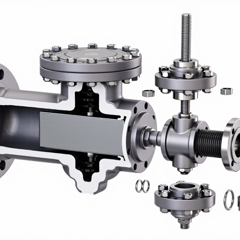
An FLS gate valve controls flow by moving a gate across the bore, rather than turning a plug inside the passage. In a typical slab-gate design, the stem drives a flat gate between two seats. When open, the gate’s opening aligns with the bore, leaving a nearly straight flow path. When closed, the solid section blocks it. Simple geometry. The body contains pressure; the bonnet guides and seals the stem, while the seats form the sealing interfaces. Handwheel or actuator movement supplies the force, but pressure and friction affect how much force is needed.

API Specification 6A gives pressure-rating classes from 2,000 to 20,000 psi for applicable wellhead equipment, including valves. That range is a design rating, not permission to exceed a valve’s marked limit; confirm the specific nameplate and service conditions. During operation, pressure may load the gate against a seat, helping sealing in some designs while increasing friction. Seat materials, surface finish, and debris therefore matter. Small details. A trapped particle can score a sealing surface, and uneven wear can undermine the assumption that both seats seal equally. API Spec 6A and ISO 10423 provide the relevant wellhead-equipment requirements; inspection should still follow the valve’s documented procedures and operating history.
The Ten Main Components and Their Individual Functions

A gate valve’s ten main components work together to control flow and contain pressure. The body forms the main pressure boundary and directs fluid through the valve. The bonnet closes the body opening and supports the stem assembly. Inside, the gate moves across the flow path to stop or allow flow. The seats provide sealing surfaces for the gate when the valve is closed. A close fit matters.

The stem transfers movement from the operator to the gate. In a rising-stem design, the stem nut converts rotation into upward or downward travel. A handwheel or actuator supplies the turning force. Packing seals around the moving stem to limit leakage at the bonnet. Small details matter. Packing that is too loose may leak; excessive compression can make operation difficult.

A bonnet gasket seals the joint between the body and bonnet. End connections attach the valve to the pipeline, using the connection style specified for the installation. These ten components may look straightforward, but wear or poor adjustment in one area can affect the whole valve. During inspection, check for leakage, restricted movement, and damage to sealing surfaces. Exact layouts and materials vary by design, so this list should not replace the valve’s service documentation. I would be cautious about assuming every gate valve is assembled identically.

Top 10 Gate Valve Components and Their Functions

The chart groups ten common gate-valve components by their primary function. Counts refer to the components listed here, not to performance or the exact configuration of every valve design.

Components shown: Pressure boundary—body and bonnet; flow isolation and sealing—gate and seat rings; motion transmission—stem, stem nut, and yoke; stem sealing—packing and gland; manual input—handwheel. Component details vary by valve design.

How the Components Work Together During Opening and Closing

When an FLS gate valve opens, movement starts at the handwheel or actuator. Its rotation turns the stem, which raises the gate through the bonnet. In a rising-stem design, the stem visibly moves upward; other designs keep it within the valve. The gate lifts clear of the flow path, leaving a relatively unobstructed passage. That takes force.

The body contains pressure, while the bonnet supports and seals around the moving stem. Guides help keep the gate aligned as it travels. The seats on either side provide the sealing surfaces. When fully open, the gate should not rub heavily against them; misalignment or debris can cause wear. Small details matter.

Closing reverses the movement. The stem drives the gate down between the seats, and the gate’s sealing faces press against them to restrict flow. Depending on the design and pressure conditions, pressure may help energize the seal. Operators should close steadily rather than use the valve to regulate flow, since partial opening can damage sealing surfaces. The exact motion and sealing arrangement vary by valve configuration, so inspection should follow the equipment’s documented procedure. A slight stem drag is easy to dismiss, but it can signal rising friction or an alignment issue.

Top 10 FLS Gate Valve Components and Their Functions - How the Components Work Together During Opening and Closing

No. Component Main Function During Opening During Closing
1 Valve body Contains the flow passage and supports the internal components as part of the pressure boundary. Provides the passage through which fluid flows as the gate moves clear of the flow path. Houses and supports the gate and seats as the valve moves toward its closed position.
2 Bonnet Closes the top of the body and provides a passage for the stem; its joint is part of the pressure boundary. Encloses the rising gate and guides or supports the stem assembly, depending on the design. Keeps the stem assembly supported while the gate moves down into the body.
3 Gate The movable closure element that travels across the flow passage; its shape varies by valve design. Moves out of the flow path to permit flow through the valve. Moves into the flow path and engages the seating surfaces to shut off flow.
4 Seat rings or seating surfaces Provide the surfaces that mate with the gate to restrict flow when the valve is closed. Remain alongside the gate as it withdraws; the gate separates from the sealing surfaces. Contact the gate to form the intended shutoff interface. Sealing performance depends on design and condition.
5 Stem Transmits movement from the operating mechanism to the gate. Moves the gate away from the seats; in a rising-stem design, the stem rises as the valve opens. Drives the gate toward the seats; in a rising-stem design, the stem lowers as the valve closes.
6 Stem nut or stem drive Engages the stem threads to convert actuator rotation into stem travel in designs that use this arrangement. Turns in the opening direction and advances the stem and gate away from the seats. Turns in the closing direction and advances the stem and gate toward the seats.
7 Stem packing Forms a seal around the stem where it passes through the bonnet to help limit external leakage. Accommodates stem movement while maintaining contact around the moving stem. Continues sealing around the stem as it returns toward the closed position.
8 Gland and follower Apply and retain compression on the stem packing in designs with an adjustable packing gland. Keep the packing in place while allowing the stem to travel. Continue to hold the packing around the stem; packing adjustments should follow the manufacturer’s procedure.
9 Operating device Supplies the input force or torque; depending on the installation, it may be a handwheel, gearbox, or powered actuator. Turns or drives the stem mechanism in the opening direction. Turns or drives the stem mechanism in the closing direction and stops at the specified operating position.
10 Gate guides Help keep the gate aligned during travel in designs that include guides. Guide the gate as it lifts or moves clear of the seating area. Help direct the gate into alignment with the seats as it moves down.

Operating sequence: The operating device turns or drives the stem mechanism; the stem moves the gate across the flow passage. On opening, the gate withdraws from the seats. On closing, it returns to the seats to restrict flow. Component details vary by gate style, stem arrangement, and actuator configuration.

Sealing, Pressure Control, and Material Considerations

A gate valve’s sealing performance depends on the gate, seats, stem, packing, and bonnet. The body contains pressure, while the bonnet closes its upper opening. The gate moves between the seats to stop or allow flow. Seat contact must be even; small debris can leave a leak path. These parts work together, but wear is rarely uniform.

The stem transfers handwheel or actuator movement to the gate. A stem nut converts rotation into travel, while the packing seals around the moving stem. The gland compresses that packing; overtightening can make operation stiff. Bonnet bolts hold the pressure boundary together.

For pressure control, gate valves are generally intended for fully open or closed service, not steady throttling. Partial opening can cause vibration and damage.

Material selection should match the fluid, temperature, and pressure rating. The body and gate need suitable strength, while seat and packing materials must tolerate the service conditions. Corrosion resistance matters, but it does not replace inspection.

Tips: Check for stem leakage and uneven seat wear during maintenance. Confirm packing adjustment against the valve maker’s instructions; a snug fit is not always a better seal.

Inspection and Maintenance of Critical Valve Components

Top 10 FLS Gate Valve Components and Their Functions

Inspection and Maintenance of Critical Valve Components

Reliable inspection starts with the stem, packing, bonnet joint, gate, and seats. A worn packing set may leave a faint leak or dried residue around the stem. Look closely. Check the stem for scoring and the packing gland for uneven compression. Do not tighten it blindly; excess compression can increase operating torque and damage packing. Inspect bonnet bolts and nearby surfaces for corrosion, seepage, or signs of movement.

During a planned shutdown, qualified personnel can check gate and seat surfaces for pitting, debris, or uneven wear. Confirm the valve travels fully without binding, and record operating effort and any leakage. The U.S. EPA’s 1995 Protocol for Equipment Leak Emission Estimates attributes roughly 60% of refinery equipment-leak emissions to valves. That estimate is refinery-specific, not a prediction for every installation. Still, it shows why small stem leaks deserve attention.

A clean exterior does not prove the internal sealing surfaces are sound. Inspection has blind spots. Compare findings over time, because a gradual rise in operating torque may matter more than one isolated reading. Follow site isolation and pressure-release procedures before opening a valve, and use the applicable service manual for inspection limits. Even careful checks cannot reveal every hidden defect, so document what was not inspected as clearly as what was.

Have Questions?

Talk to a product specialist today: 1-800-308-6788

Snake Tray Catalog

snake tray® CATALOG

the new catalog is here. AVAILABLE IN PRINT AND ONLINE.

DOWNLOAD A PDF REQUEST A PRINTED COPY
CALL US TODAY