What Is a Digital Signal Isolator and How Does It Work?
A Digital Signal Isolator transfers logic signals across an electrical barrier without creating a direct conductive path. That small separation matters in motor drives, medical equipment, and industrial controllers, where noisy voltage differences can disrupt measurements or damage electronics. The barrier may use capacitive or magnetic coupling. On one side, a transmitter encodes changing logic states; across the barrier, a receiver reconstructs them. The bits cross. The current path does not.
The engineering evidence is concrete. Texas Instruments’ ISO7841 datasheet specifies isolation withstand voltage up to 5.7 kVrms and data rates up to 100 Mbps. These are device ratings, not guarantees for every circuit; board layout, insulation spacing, and operating conditions still matter. IEC 60747-17 sets requirements for magnetic and capacitive couplers used as isolators, offering designers a standards-based reference. Analog Devices engineer David Krakauer has published guidance on isolation design. A fair paraphrase of its practical lesson is: “Choose the barrier for the system’s real safety and signal needs, not one headline rating.” That is a paraphrase, not a verbatim quotation.
The distinction is easy to miss. A fast isolator can still fail a design if common-mode transients overwhelm it, or if the PCB weakens the isolation barrier. Look closely at the datasheet. Compare working voltage, transient immunity, timing, and package layout. Then check the whole board. The component is only one part of the barrier. Manufacturers’ test data help, but real-world conditions can be less tidy than the lab. That deserves a second look.
What a Digital Signal Isolator Separates: Logic Signals and Ground Domains
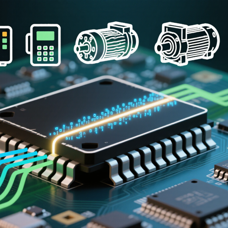
A digital signal isolator transfers logic information while keeping two ground domains electrically separate. One side may belong to a sensor circuit; the other may connect to a processor. Their grounds are not joined by a signal wire. That boundary matters.
Inside the isolator, changing logic levels are converted into brief pulses or fields across an insulation barrier. Depending on its design, the device may use capacitive, magnetic, or optical coupling. The receiving circuit detects the change and recreates a logic level using its own supply and ground. For example, a controller can read a sensor’s high or low output without directly sharing the sensor’s ground reference.
This separation helps limit unwanted current between circuits when their ground potentials differ. It can also reduce the effect of some fast electrical disturbances. But isolation is not a cure-all. The isolator still has limits for voltage, timing, and transient exposure, so its specifications must match the circuit. A detail that is easy to overlook: both sides may need separate power supplies. And even a well-chosen part cannot fix poor board layout or unsuitable wiring.
How Capacitive, Magnetic, and Optical Barriers Transfer Digital Data
A digital signal isolator transfers logic states between circuits without a direct conductive connection. One side converts an input into a changing signal; the other detects it and rebuilds a digital output. The barrier helps interrupt unwanted current paths, while preserving communication. It does not automatically isolate power, so circuit design still matters.
Capacitive isolators encode data as changing electric fields across a thin insulating layer. A receiver senses those transitions and reconstructs the logic levels. Magnetic isolators use changing magnetic fields, often created by small coils on opposite sides of the barrier. Both methods need transitions to carry information, so internal encoding can represent steady high or low states. That detail is easy to miss. Optical isolators instead turn electrical input into light, then use a photosensor to detect it. A tiny light pulse crosses the gap.
Each method has tradeoffs. Capacitive and magnetic designs can support fast data rates, but engineers must check noise immunity, timing, and common-mode transient ratings. Optical barriers provide a clear physical separation, yet LED aging and power use may matter in some designs. A receiver can misread a transition if noise overwhelms the signal. Layout counts, too: keep suitable spacing around the barrier and follow the device’s specifications. The best choice depends on signal speed, isolation needs, and the surrounding electrical environment.
How Encoding and Edge Detection Reconstruct Signals Across the Barrier
What Is a Digital Signal Isolator and How Does It Work?
How Encoding and Edge Detection Reconstruct Signals Across the Barrier
A digital signal isolator transfers logic information while keeping two circuits electrically separate. Instead of carrying a steady voltage directly across the barrier, its transmitter encodes input changes as brief pulses. Depending on the design, those pulses cross through capacitive, magnetic, or optical coupling. The barrier blocks a direct conductive path, but information still gets through.
On the receiving side, a detector identifies each pulse or edge and restores the corresponding high or low state. For example, when a controller’s output changes from low to high, the isolator sends a coded transition. The receiver detects it and switches its output after a small propagation delay. A refresh scheme can also preserve a steady logic level when no new edge arrives. This is signal reconstruction, not a perfect copy of every electrical detail. Timing shifts, narrow pulses, and noise can matter, so check the device’s pulse-width and data-rate limits.
Tips: Match the isolator’s logic levels and data rate to your circuit. Keep traces short near fast edges, and test timing under real load conditions. Small delays add up. Don’t assume the output changes instantaneously.
Example Datasheet Ratings: IEC 60747-17, 5 kVrms, and 100 kV/µs CMTI
A digital signal isolator transfers logic signals across an electrical barrier without a direct conductive connection. That barrier helps protect low-voltage control circuits from hazardous voltages and ground shifts. Datasheets may cite IEC 60747-17, a standard covering insulation requirements for magnetic and capacitive couplers. The reference matters, but it does not make every rating interchangeable.
A 5 kVrms figure usually describes an isolation withstand test under stated conditions. It is not automatically the voltage the device can tolerate continuously. Check the test duration, insulation category, and working-voltage rating. Numbers need context. CMTI, or common-mode transient immunity, describes how quickly the voltage between the isolator’s two sides can change without causing a false output. At 100 kV/µs, that voltage can rise by 100,000 volts in one microsecond. A sharp switching edge can create that kind of stress. The stated CMTI applies under specified test conditions, including the signal state and test setup. Board layout still matters: keep barrier spacing clear and limit noisy return paths. I sometimes focus too much on the headline rating; the small-print conditions can change the design decision.
Where Isolators Are Used: Motor Drives, Medical Equipment, and Industrial I/O
A digital signal isolator transfers logic signals across an electrical barrier without a direct conductive connection. Capacitive or magnetic coupling carries pulses between circuits while helping block hazardous voltage and ground-loop currents. This matters in motor drives, where fast-switching power devices create sharp voltage changes and electrical noise. Isolated control and feedback signals help protect low-voltage controllers.
Noise is real.
The International Energy Agency’s 2011 report, Energy-Efficiency Policy Opportunities for Electric Motor-Driven Systems, estimates that motor-driven systems use about 45% of global electricity. That scale makes dependable drive control important, though isolation alone cannot improve motor efficiency.
Medical equipment uses isolation to separate patient-connected measurement circuits from other electronics. A sensor lead may carry a tiny signal beside switching power supplies, so barrier performance and careful circuit layout both matter. IEC 60601-1 sets general safety requirements for medical electrical equipment; designers must assess the complete device, not treat an isolator as a safety guarantee.
Industrial I/O faces another practical problem: long cables can connect equipment with different ground potentials. Isolated inputs and outputs can limit fault-current paths and reduce interference reaching a controller. But barriers add cost and can affect signal timing. Engineers still need to check working voltage, transient ratings, creepage distance, and the system’s actual noise conditions.