How to Choose the Right Pneumatic Butterfly Valve
Choosing the right Pneumatic Butterfly Valve begins with the process, not the catalog photo. Check the medium, operating pressure, temperature range, and required flow before comparing models. A valve moving clean water may behave differently with abrasive slurry or hot process gas. Small details matter. Record the pipe size, flange standard, and available instrument air pressure. Then confirm whether the valve needs to throttle flow or provide simple on-off service. These checks help prevent a common mistake: choosing by diameter alone.
Valve applications engineer Daniel Mercer offers a useful reminder: “Match the valve, actuator, and process as one operating system.” Treat that as a selection principle, not a substitute for verified specifications. Compare disc and seat materials against the actual fluid, and check the actuator’s torque at the minimum available air pressure. Consider fail-open or fail-closed behavior, control signals, cycle frequency, and access for maintenance. A compact actuator can look convenient, yet leave too little torque margin. That deserves a second look.
Good selection is practical. Picture the valve installed between two flanges, with an actuator above it and a technician needing room to remove the assembly. Confirm face-to-face dimensions, mounting compatibility, and any accessory requirements before ordering. Ask the supplier for documented pressure, temperature, leakage, and torque data. If those figures are unclear, pause. This guide explains how to compare the key options, identify trade-offs, and choose a Pneumatic Butterfly Valve that fits the real operating conditions—not just the initial specification.
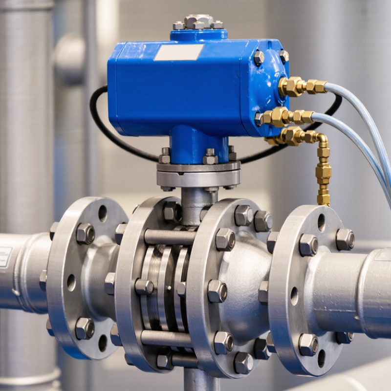
Define the Process Requirements and Operating Conditions
A pneumatic butterfly valve should match the actual process, not just the pipe diameter. Write down the fluid, normal and peak pressure, temperature range, flow rate, and expected cycling frequency. A clean-water line and a slurry line can behave very differently. Suspended particles may wear the seat or collect around the disc. Check chemical compatibility for both the body and the sealing materials. Small details matter.
Operating conditions shape the valve and actuator selection. Note the available instrument-air pressure and whether the valve must fail open, fail closed, or stay in place after air loss. Frequent cycling can call for different actuator sizing than occasional isolation. Also consider pressure drop, installation space, and whether the disc could interfere with nearby pipework. Compare these conditions with current product data, and ask a qualified supplier to verify the required operating torque. A rough estimate can miss changes caused by pressure or deposits.
Tips: Use real operating records where possible, including startup peaks and temperature swings. If data is incomplete, say so rather than treating an assumption as fact. I have seen selection discussions focus too much on nominal pipe size; it is an easy shortcut, but not always a reliable one. Check the valve’s limits against the toughest credible operating condition.
How to Choose the Right Pneumatic Butterfly Valve - Define the Process Requirements and Operating Conditions
Use the examples below to organize process data before selecting a valve and pneumatic actuator. Values are typical screening considerations, not universal design limits; confirm the final selection against the applicable piping code, valve specifications, and operating data.
| Process Requirement | What to Define | Example Operating Data | Selection Implication | Information to Verify |
|---|---|---|---|---|
| Fluid and phase | Identify the medium and whether it is a liquid, gas, vapor, or multiphase flow. | Cooling water; liquid at normal operating conditions. | Confirm body, disc, stem, and seat compatibility with the fluid and any treatment chemicals. | Fluid composition, concentration, pH, contaminants, and any cleaning chemicals. |
| Temperature | Record normal, minimum, maximum, and upset temperatures. | Cooling-water service: 10–40 °C normal; 5–50 °C design range. | Seat material and actuator accessories must suit the full temperature range, not only the normal value. | Temperature at the valve, thermal cycling, heat tracing, and exposure to ambient extremes. |
| Pressure and differential pressure | Specify upstream and downstream pressures for operating, shutoff, and transient conditions. | Water line at 6 bar(g) operating pressure; maximum shutoff differential pressure to be confirmed. | Check the valve pressure rating and size the actuator for the maximum required seating or unseating torque. | Pressure class, surge or water-hammer events, vacuum conditions, and pressure at both sides of the closed valve. |
| Flow rate and pipe size | Provide minimum, normal, and maximum flow rates, pipe inside diameter, and allowable pressure drop. | Water flow varies from 20 to 100 m³/h in a DN100 line; allowable valve pressure drop is 0.3 bar at normal flow. | Determine valve size and flow coefficient from the actual flow conditions; do not select by pipe size alone. | Fluid density, viscosity, vapor pressure, flow direction, and whether the valve will throttle or only isolate. |
| Solids and deposits | Describe suspended particles, fibers, scale, or sediment. | Water containing occasional fine sediment, with no long fibers. | Consider disc clearance, seat design, wear resistance, and whether solids could obstruct closure. | Particle size, concentration, abrasiveness, settling behavior, and cleaning or flushing requirements. |
| Corrosion and material compatibility | Assess corrosion, erosion, and chemical exposure for all wetted parts. | Neutral treated water with low chloride concentration. | Select body, disc, stem, and seat materials for the actual chemistry; avoid assuming that all water services are equivalent. | Chlorides, dissolved gases, chemical additives, galvanic couples, and corrosion allowance requirements. |
| Shutoff and leakage | Define the required isolation performance and any leakage acceptance criteria. | Routine on/off isolation; leakage class or test standard specified by the project. | Choose a resilient-seated or high-performance design as appropriate to the pressure, temperature, and leakage requirement. | Applicable test standard, seat directionality, expected cycle frequency, and whether bidirectional shutoff is required. |
| Control duty | State whether the valve is for on/off service, modulating control, or emergency isolation. | Modulating service with a 4–20 mA position command and position feedback. | For modulating duty, confirm controllable range, actuator positioning accuracy, and compatibility with the control signal. | Required response time, control accuracy, cycling frequency, and any need for a positioner or limit switches. |
| Air supply | Specify instrument-air pressure, quality, and availability at the actuator. | Clean, dry instrument air available at 5.5 bar(g) during normal operation. | Verify actuator output torque at the minimum available air pressure, including losses from accessories. | Minimum and maximum supply pressure, air quality requirements, tubing size, and supply reliability. |
| Fail position and safety | Define the required valve position on loss of air, electrical power, or control signal. | Fail-closed requirement for an isolation line. | Select the appropriate spring-return or other fail-safe actuator arrangement and confirm its available torque throughout travel. | Hazard analysis, safe state, stored-energy requirements, closure time, and any manual override requirement. |
| Installation and environment | Record orientation, available space, pipe connection, ambient conditions, and enclosure needs. | Horizontal DN100 line indoors; ambient temperature 5–40 °C; limited actuator clearance. | Check face-to-face dimensions, actuator envelope, access for maintenance, and protection against moisture or dust. | Flange or wafer/lug connection, pipeline alignment, nearby obstructions, vibration, and required enclosure rating. |
Before final selection: provide the valve supplier with the complete operating envelope, including maximum differential pressure, temperature extremes, required leakage performance, and minimum available air pressure. Confirm valve torque and actuator sizing for the specified duty and safety margin.