How to Choose the Right 4 Pin Female Connector
Choosing the right 4 Pin Female Connector is more than matching four holes to four pins. The connector must suit the electrical load, cable size, environment, and mating system. A careful selection protects signal quality, reduces downtime, and prevents avoidable installation problems.
Begin with the application details. Check the rated voltage and current against the equipment’s real operating conditions, not only its average demand. Confirm the pin layout, contact spacing, wire gauge, and termination method. A connector may look identical while using different keying or pin assignments. That mistake can damage a circuit. It happens more easily than expected.
Environmental conditions also matter. For outdoor equipment, review the IP rating, sealing design, UV resistance, and operating temperature range. Industrial machines may require vibration resistance, locking clips, and strong strain relief. In compact control panels, housing size and cable-bend space can decide whether installation is practical. Materials deserve attention too. Gold-plated contacts may support reliable low-current signals, while suitable copper alloys can offer balanced conductivity and durability.
Reliable selection depends on manufacturer datasheets, verified drawings, and credible testing information. Look for mating-cycle ratings, insulation specifications, contact resistance, and compliance details. Do not rely on product photos alone. They rarely show tolerance, locking strength, or internal construction.
A useful check is a physical trial. Measure the cable, inspect the latch, and test the connection under realistic vibration and temperature conditions. The perfect connector on paper may still be awkward in the field. Review the choice before purchasing in volume. That small pause can prevent expensive rework and uncertain performance.
Understanding the Structure and Purpose of a 4-Pin Female Connector
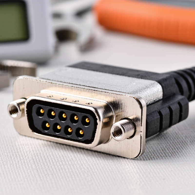
A 4-pin female connector contains four recessed contact positions inside an insulating housing. Each cavity holds a metal terminal, while the outer shell controls alignment and protects the connection. A latch or locking tab prevents accidental separation. The female design shields exposed contacts, which helps reduce bending and unwanted contact during handling. Small details matter here.
Its four pins may carry power, ground, data, or control signals. Never assume the pin order. Check the wiring diagram, voltage rating, current capacity, and wire gauge before choosing one. The 2024 Global Connector Market Analysis projects steady market growth through 2030, driven by vehicle electronics, industrial controls, and connected equipment. That growth reflects demand for compact, reliable interfaces, not just more contact positions.
In practical use, inspect keying, terminal plating, strain relief, and environmental sealing. IEC 60512 test methods evaluate connector performance through mating, vibration, temperature, and electrical tests. An IP-rated housing may suit dusty or damp equipment, but its rating depends on the complete mated assembly. I have seen connectors fail because the housing fit perfectly, while the terminal size was wrong. That mistake is easy to miss. A better choice matches the connector’s structure to its real electrical and mechanical conditions.
How to Choose the Right 4-Pin Female Connector
Understanding the structure and purpose of a 4-pin female connector starts with identifying the signal requirements. A common USB 2.0 four-contact arrangement uses VBUS, D−, D+, and GND. The chart compares the standardized USB 2.0 signaling modes that may use this four-contact structure.
Low-speed signaling operates at 1.5 Mbps, full-speed signaling at 12 Mbps, and high-speed signaling at 480 Mbps. When selecting a 4-pin female connector, verify the pin arrangement, contact plating, rated current, mechanical fit, shielding, and whether the connector assembly supports the required signal speed. The four-pin layout alone does not guarantee high-speed performance.
Identifying Electrical, Mechanical, and Environmental Requirements
How to Choose the Right 4 Pin Female Connector
Identifying Electrical, Mechanical, and Environmental Requirements
A four-pin connector is not automatically suitable for four circuits. Pin count only describes contact quantity. Current, voltage, signal speed, and insulation requirements still matter. A 2024 global connector market analysis estimated automotive applications at approximately one-third of total demand. That growth increases the need for reliable vibration resistance and stable contact pressure. Check the datasheet’s current rating at the actual wire size and ambient temperature. Ratings often decline as temperature rises.
Mechanical fit deserves equal attention. Measure panel thickness, keying position, latch clearance, and cable bend radius. Confirm the mating cycle requirement, especially for serviceable equipment. IPC/WHMA-A-620 provides widely used workmanship criteria for cable and wire-harness assemblies. However, it does not replace the connector manufacturer’s performance data. A connector can fit perfectly and still fail under repeated movement. I have seen overlooked latch clearance damage housings during maintenance.
Environmental conditions should guide the sealing choice. IEC 60529 defines IP67 as dust-tight protection and temporary immersion up to one metre for 30 minutes, under specified test conditions. That rating does not guarantee resistance to oil, chemicals, salt spray, or continuous underwater use. Use the relevant material and corrosion data. Also verify operating temperature, ultraviolet exposure, and condensation risk. A 2023 industrial electronics report identified harsh-environment applications as a major reliability concern, but field conditions remain less predictable than laboratory tests. Leave a safety margin. That part is often underestimated.
Comparing Connector Types, Materials, and Contact Configurations
Choosing a 4 pin female connector starts with its contact configuration. A four-position layout may carry power, signals, or both. For sensors, two pins often handle supply and ground, while the remaining contacts transmit data. A keyed housing reduces insertion errors. However, pin count alone does not guarantee compatibility.
Connector types should match movement, moisture, and service conditions. Board-mount versions suit compact equipment, while cable connectors tolerate repeated assembly. Circular housings generally protect contacts better in vibration-heavy environments. For materials, copper alloys offer strong conductivity and spring recovery. Gold plating supports low-level signals, while tin plating can reduce cost in stable, indoor applications. The wrong choice may look acceptable during testing, then fail after months of cycling.
Market evidence supports careful selection. MarketsandMarkets forecasts the global connector market to grow at about 5.5% annually through 2028, driven partly by automotive electronics and industrial automation. Bishop & Associates also reports continued demand for higher-density and more reliable interconnects. These trends make contact force, temperature rating, and sealing more important than appearance.
Tips: Check the mating cycle rating, wire gauge range, and current per contact. Test the complete assembly under heat, vibration, and humidity. Do not trust a catalog photograph. Measure the key, pitch, and latch position. A small mismatch can stop production. I still find contact configuration is often underestimated, especially when power and data share one compact housing.
Checking Compatibility, Ratings, and Installation Specifications
How to Choose the Right 4 Pin Female Connector
Checking compatibility starts with more than counting four pins. Confirm the pin layout, contact spacing, keying, housing shape, and mating connector. A female connector can look correct while using a different pin arrangement. I once treated a matching pin count as proof of compatibility. It was not. Check the equipment drawing and connector datasheet before ordering. Measure twice.
Review the electrical ratings under real operating conditions. Current capacity may drop when wires are small, airflow is limited, or several contacts carry power together. Verify voltage, temperature range, insulation resistance, and contact material. Select terminals that match the intended wire gauge. For outdoor or dusty equipment, inspect the stated sealing level and cable-entry design. Do not rely on appearance alone.
Installation specifications deserve equal attention. Confirm the required crimp tool, stripping length, insertion force, locking method, and strain relief. A loose crimp can create heat, vibration faults, or intermittent signals. After assembly, perform a continuity test and gently pull each wire. Check polarity before applying power. It is easy to overlook grounding. Document the pinout, wire colors, and test results for future maintenance. The installation may still need adjustment after its first vibration or temperature test.
Selecting a Reliable 4-Pin Female Connector for Your Application
Selecting a reliable 4-pin female connector starts with the application, not the product photo. Define the signal type, current, voltage, wire gauge, and available space. A connector carrying a sensor signal needs different protection from one feeding a small motor. Check the pin layout carefully. A reversed key or mirrored drawing can cause costly rework. I once trusted a familiar housing without checking the locking clearance. It fit electrically, but vibration loosened the connection. That mistake still influences my inspection process.
Review the datasheet for contact resistance, mating cycles, insulation rating, and temperature range. For outdoor equipment, examine sealing details and the stated ingress protection level. Do not assume a rubber seal makes every assembly waterproof. Cable entry matters. Choose terminals that match the conductor size and crimp method. A firm crimp should hold without cutting strands. Pull-test sample assemblies before installation, then inspect them under magnification. Small defects become intermittent faults later.
Reliability also depends on testing the complete cable assembly. Cycle the connector while the equipment runs. Add vibration, thermal changes, and gentle cable movement when those conditions exist in service. Record failures, even awkward ones. A connector may pass a bench test yet fail after repeated bending near the strain relief. I would compare two samples, not one, because production variation is easy to underestimate. Leave room for gloves and maintenance tools. Selection is rarely perfect on the first attempt. Recheck the choice after field feedback.