Choosing the right Continuous carbon fiber production line in 2026 requires more than comparing equipment prices. It demands a clear understanding of fiber type, resin compatibility, throughput, temperature control, and final-part quality. A line that performs well during a factory demonstration may behave differently under continuous production pressure. Small details matter.
In practical evaluations, engineers should inspect tension stability, impregnation uniformity, heating zones, cooling accuracy, and winding performance. Ask for verified production data, not only attractive brochures. Check how the supplier measures fiber volume fraction, void content, line speed, and dimensional consistency. These figures reveal whether the system can support real manufacturing targets. Operator training also deserves attention. Complex equipment can lose efficiency when daily adjustments depend on one experienced technician.
A reliable supplier should provide traceable testing, clear maintenance schedules, spare-part support, and realistic energy estimates. Independent validation can strengthen the decision, especially when comparing new automation features. Still, no checklist removes every uncertainty. Material behavior may change with humidity, batch quality, or recycled content. That point is often underestimated. Therefore, this guide examines how to select a Continuous carbon fiber production line for 2026, while recognizing both proven practices and unresolved risks. The best choice is not always the fastest line. It is the system that delivers stable quality, measurable productivity, and manageable long-term service demands.
A 2026 production line should match measurable performance targets, not attractive catalog language. For high-performance continuous carbon fiber, set a tensile strength range of 3–7 GPa and a tensile modulus range of 230–600 GPa. These figures demand stable precursor conversion, controlled oxidation, and accurate carbonization temperatures. Small temperature shifts can change molecular alignment and final stiffness.
Line selection should include precise tension control across every furnace zone. Uneven tension may create weak sections, even when average test results look acceptable.
Ask for data from multiple production lots. Test strength and modulus using a recognized standard, controlled gauge length, and documented humidity conditions. The testing details matter.
Tow size also affects throughput, heat transfer, and defect risk. A larger tow may improve output, but it can complicate uniform treatment. I have seen excellent laboratory results fail during scale-up. That possibility deserves attention. Select a line with adjustable residence time, real-time temperature recording, and accessible maintenance points. Do not judge performance from one impressive sample.
A continuous carbon fiber line must match the target fiber volume and production speed. For 20–35% fiber volume, a compact impregnation section may provide stable resin wet-out. Higher volumes, around 40–60%, usually need stronger tension control, improved heating, and longer consolidation zones. Dry fiber spots become more likely when the resin cannot flow quickly enough.
Throughput depends on more than line speed. Tow count, resin viscosity, heating capacity, cooling length, and puller force work together. A line running at 12 meters per minute may produce less usable material than a slower line with better impregnation. Check the full process path: creel alignment, spreading, impregnation, sizing, consolidation, cooling, and winding. Small alignment errors can create waviness.
During equipment trials, inspect fiber distribution across the tape width. Use microscopy, burn-off testing, and tensile testing to verify fiber volume and void content. Record temperature stability every few minutes, not only at the start. A spreadsheet can look convincing and still mislead. I have seen promising samples fail after cooling because internal stress was overlooked. Leave room for adjustment. A line designed only for today’s resin and tow may become restrictive when throughput targets change. Reliable selection comes from pilot runs, repeatable measurements, and operators who understand the material’s behavior.
Choosing a continuous carbon fiber line for 2026 requires tighter process control, not simply higher output. A 2024 carbon fiber market report projects the sector to grow at about 8% annually through 2028. That growth increases pressure on manufacturers to reduce scrap and stabilize quality.
Target tow tension within ±1% of the setpoint. Small variations can create waviness, resin-rich zones, or uneven spreading. A 12K tow moving through ceramic guides should feel steady, without visible flutter. Use closed-loop load cells, powered creels, and recipe-based tension settings. Calibrate each sensor before production. Real factories are rarely perfect.
Add automatic fiber-break detection. Optical sensors can identify missing filaments, while tension signals can confirm a true break. The control system should stop or slow the line within seconds, record the event, and display the affected position. The 2023 Composites Manufacturing Industry Survey reported that material waste and process consistency remain major operational concerns. Detection must therefore work during acceleration, splice changes, and dusty shifts.
Do not trust one sensor alone. False alarms can interrupt stable production. Combine tension, optical, and line-speed data, then validate alerts with cut-section inspections. A 2024 advanced-composites market analysis estimated aerospace and automotive demand as key growth drivers, where traceability and repeatability matter. Operators should review alarm histories weekly, because a perfect dashboard can still hide a poorly aligned guide.
| Selection Dimension | Practical Reference Range | Recommended 2026 Target | Verification Method | Why It Matters |
|---|---|---|---|---|
| Tow-tension stability | Process tension varies with tow size, speed, creel friction, guides and material sizing. | Closed-loop control within approximately ±1% of the operator-set tension during steady-state production. | Run a continuous production trial and record tension at the creel, spreader and take-up. Report average, minimum, maximum and standard deviation. | Stable tension reduces tow slack, excessive compaction, filament damage and variation in fiber placement. |
| Tension measurement | Load-cell capacity should be selected according to the tow and process range rather than using one oversized sensor for every product. | Use a calibrated load cell with a measurement range appropriate to the target tow tension; keep normal operation away from the bottom and top limits. | Check calibration with traceable test weights or a certified reference device before and after the trial. | An oversized sensor can reduce resolution, while an undersized sensor can overload or saturate during starts and stops. |
| Tow-size compatibility | Commercial carbon-fiber tows are commonly identified by nominal filament counts such as 1K, 3K, 6K, 12K, 24K and 50K; actual availability varies by material specification. | Select a line that supports the intended filament-count range without changing the basic tension-control architecture. | Confirm compatible tow width, filament count, sizing type, spool geometry and maximum package mass in the equipment specification. | Different tow sizes require different guide geometry, spreading force, tension settings and detection thresholds. |
| Automatic fiber-break detection | Detection may use optical, tension-based or combined sensing. A single sensor can miss breaks hidden inside a wide tow. | Use automatic detection with an alarm, event timestamp and controlled line stop or safe-speed mode. | Introduce controlled single-filament and partial-tow breaks at representative line speeds. Confirm detection, alarm, response and restart behavior. | Early detection prevents long defect sections and reduces the risk of undetected strength or continuity loss. |
| Detection response time | The required response depends on line speed and the maximum acceptable defective length. | Set the response requirement from the formula: response time ≤ allowable defect length ÷ line speed. Validate the complete sensor-to-stop sequence. | Example: at 60 m/min, material moves 1 m per second. A 100 mm maximum undetected length requires a response of about 100 ms or less. | Response time should be specified as a measurable production requirement rather than described only as “real-time.” |
| Line-speed range | Stable speed depends on tow size, process temperature, impregnation method, winding geometry and allowable tension variation. | Specify both the normal operating speed and the validated minimum and maximum speeds for each tow family. | Test acceleration, steady running, deceleration and emergency-stop recovery using production-representative material. | A line that is stable only at one speed may create defects during ramp-up, recipe changes or material transitions. |
| Guide and contact surfaces | Guides should be smooth, aligned and compatible with the tow width and sizing chemistry. Damaged surfaces can abrade filaments. | Use low-friction, wear-resistant guides with no sharp edges, burrs or abrupt changes in wrap angle. | Inspect guide surfaces, measure alignment and examine the tow under magnification after a representative production run. | Mechanical abrasion can increase fuzz, broken filaments, width variation and downstream cleaning requirements. |
| Tow spreading | Spreading performance is material- and process-dependent; excessive spreading force can damage filaments. | Specify a repeatable target tow width and width variation for each tow type, rather than one universal width. | Measure tow width at several positions and speeds using calibrated imaging or a suitable contact-free gauge. | Uniform spreading supports consistent resin access, fiber volume fraction and deposition quality. |
| Control-loop performance | Open-loop braking is sensitive to spool diameter, acceleration and friction changes. | Use closed-loop tension control with recipe-based setpoints, automatic ramp profiles and limits for over-tension and slack. | Log tension and speed during spool changes, acceleration, deceleration and normal operation; review overshoot and settling behavior. | Closed-loop control compensates more effectively for changing package diameter and transient operating conditions. |
| Data logging and traceability | Useful process records include tension, speed, alarms, line state, recipe, operator action and material identification. | Record time-stamped tension and break events at a sampling rate sufficient to identify short process disturbances. | Export a production record and confirm that alarms can be linked to spool, recipe, shift and product batch information. | Traceable data simplifies root-cause analysis and helps distinguish material defects from machine-induced defects. |
| Alarm and stop logic | Different events require different actions: single-break warning, repeated breaks, high tension, low tension and sensor failure. | Configure separate warning, controlled-stop and emergency-stop thresholds with clear operator messages. | Simulate each alarm condition and verify the resulting machine state, notification, event record and restart authorization. | Clear logic prevents both unnecessary downtime and continued production after a serious continuity fault. |
| Calibration and maintenance | Sensor accuracy can drift because of mechanical loading, contamination, temperature and cable damage. | Provide documented calibration intervals, zero checks, sensor health checks and spare wear components. | Review calibration certificates, maintenance procedures, diagnostic screens and the recommended spare-parts list. | Repeatable tension control and reliable break detection require maintained sensors, clean guides and verified settings. |
| Changeover capability | Changing tow size or material can alter tension, width, sensor thresholds and guide requirements. | Use recipe-based settings for tow type, tension setpoint, speed profile, detection threshold and alarm limits. | Perform a documented changeover between at least two representative tow sizes and compare setup time and first-pass quality. | Recipe control reduces operator variation and improves repeatability across products and shifts. |
| Acceptance criteria | Acceptance should cover both steady-state quality and transient events. | Define measurable limits for tension variation, break-detection response, tow width, alarm function and restart quality before purchase. | Run a signed factory or site acceptance test using production-representative material and operating conditions. | Predefined criteria make equipment comparisons objective and reduce disputes during commissioning. |
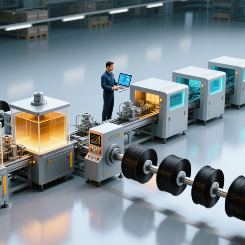
How to Choose a Continuous Carbon Fiber Line for 2026?
A continuous carbon fiber line should be judged by cured performance, not production speed alone. MarketsandMarkets valued the global carbon fiber market at about USD 4.7 billion in 2024. It projects nearly USD 6.6 billion by 2029. This growth increases pressure to qualify faster, but rushed validation can hide weak impregnation.
ASTM D3039 tensile testing gives the line a practical reality check. Prepare specimens from the cured filament, laminate, or printed section. Record fiber direction, resin content, curing temperature, and test speed. Measure tensile strength, modulus, failure location, and coefficient of variation. A clean-looking filament can still fail. Watch the fracture surface. Dry fiber streaks, resin-rich edges, and irregular tabs often reveal process instability.
Use several specimens from different production times. One impressive coupon is not enough. The 2024 Global Wind Report recorded 117 GW of new wind capacity, showing why scalable composite production matters. However, higher throughput may increase tension fluctuations and shorten resin residence time. Compare line settings beside ASTM D3039 results, not in isolation. I would also repeat testing after conditioning, because laboratory-dry samples may exaggerate confidence. The selection is imperfect when operators cannot link tensile failures to impregnation zones, cure history, or line tension.
ASTM D3039 tensile screening reference for unidirectional carbon-fiber/epoxy laminates at different fiber-volume fractions. Higher fiber content generally increases longitudinal tensile strength and modulus when impregnation and curing are uniform.
Use the chart as an engineering reference, not as a universal acceptance limit. For line qualification, test multiple specimens per condition according to ASTM D3039 and check failure location, void content, fiber alignment, impregnation quality, and cure consistency.
How to Choose a Continuous Carbon Fiber Line for 2026?
Choosing a continuous carbon fiber line in 2026 should start with measured output, not brochure speed. In pilot and production reviews, I record electricity at the line meter and divide it by saleable kilograms. This gives kWh/kg, but scrap must stay visible. A line using 18 kWh/kg can lose its advantage when 12% of material becomes waste. Our first estimate was wrong. We counted startup purge as normal production.
Track scrap by cause: broken tow, resin variation, cooling instability, and trim loss. Then calculate effective cost per accepted kilogram, including fiber, resin, labor, utilities, maintenance, and disposal. OEE adds operating reality. Availability falls during changeovers. Performance drops when operators reduce speed. Quality falls with rejected parts. A practical weekly sheet should show all three. Keep the data traceable. Use machine logs, calibrated energy meters, and signed production records.
For five-year capacity, model accepted kilograms, not rated kilograms. Use this formula: annual capacity = hours × line rate × OEE × (1 − scrap rate). Test low, expected, and high cases. Include planned maintenance and training delays. Five years is a long horizon. Spare-part lead times may change. Energy prices may shift. A second line may appear cheaper after year three if demand grows, but floor space and staffing still matter. I would challenge any spreadsheet assuming 90% OEE from month one. Real ramp-up is messier. Compare payback using discounted cash flow, then review assumptions with operators and maintenance engineers.
Fill out the form below and our team will get back to you ASAP.
Snake Tray® is Green and Proudly Powered by the Sun! Snake Tray is committed to designing and manufacturing products that have many green benefits. Our products are made of recycled goods, minimize material waste, are energy efficient, use less non-renewable resources and nest together read more…
Snake Tray® 291 Skip Lane, Bay Shore NY 11706 | PHONE: 631-674-0004 | FAX: 631-674-0010 | www.bakoselectric.com | LEGAL | MADE IN USA
© 2025 SnakeTray. All rights reserved
Fill out the form below to download your document.